10 Results
View Results:
Sort by:

The new RFEM software generation provides the option to perform stability design of tapered timber members in line with the equivalent member method. According to this method, the design can be performed if the guidelines of DIN 1052, Section E8.4.2 for variable cross-sections are met. In various technical literature, this method is also adopted for Eurocode 5. This article demonstrates how to use the equivalent member method for a tapered roof girder.
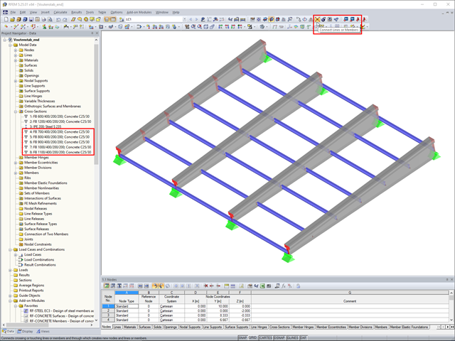
In RFEM, if you want to insert a tapered member with intermediate nodes into an existing model, the issue often arises how to determine the individual cross-section depths of the tapered members quickly. The "Connect Lines or Members" command comes in handy for this purpose.

For the stability design of members and sets of members with a uniform cross-section, you can use the equivalent member method according to EN 1993-1-1, 6.3.1 to 6.3.3. However, as soon as a tapered cross-section is available, this method can no longer be used, or only used to a limited extent. The RF-/STEEL EC3 add-on module can automatically recognize these cases and switch to the general method.
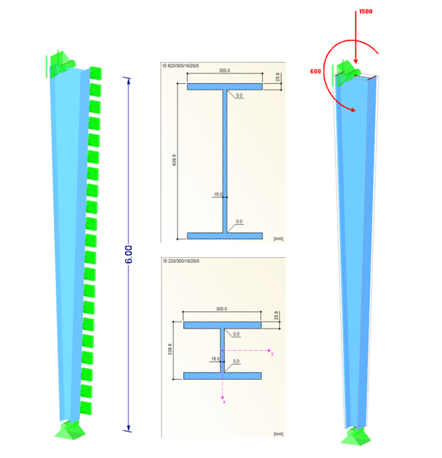
Tapers are often done using cut beam sections. When modeling, however, you have to consider certain things for checking cross‑sections and stability.
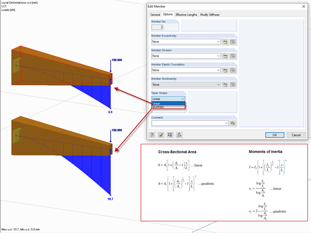
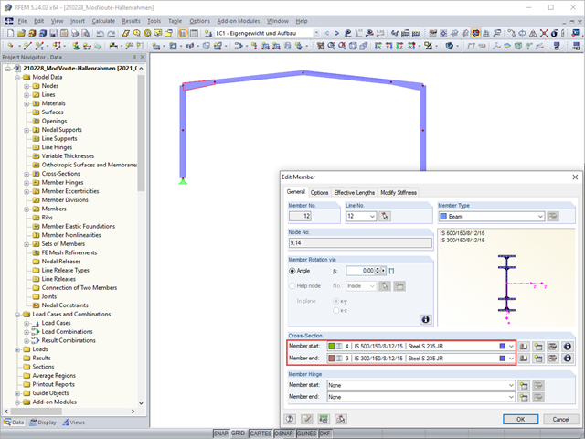
After right-clicking a member and selecting "Edit Member", you can find the "Taper Shape" option in the "Options" tab.
The following structure is covered as Example IV.10 in [1] "Comment on Eurocode 3". For a support with a linearly varying cross‑section, a sufficient ultimate limit state design (cross‑section check and stability analysis) is to be performed. Due to the unequal structural component, it is necessary to perform the stability analysis (from the main support direction) using the method according to Section 6.3.4, or alternatively, according to the second‑order analysis.

The following article describes the design of a single-span beam subjected to bending and compression, which is performed according to EN 1993‑1‑1 in the RF-/STEEL EC3 add-on module. Since the beam is modeled with a tapered cross-section and thus it is not a uniform structural component, the design must be performed either according to General Method in compliance with Sect. 6.3.4 of EN 1993‑1‑1, or according to the second-order analysis. Both options will be explained and compared, and for the calculation according to the second-order analysis, there is an additional design format using Partial Internal Forces Method (PIFM) available. Therefore, the design is divided into three steps: design according to Sect. 6.3.4 of EN 1993‑1‑1 (General Method), design according to the second‑order analysis, elastic (warping torsion analysis), design according to the second‑order analysis, plastic (warping torsion analysis and Partial Internal Forces Method).
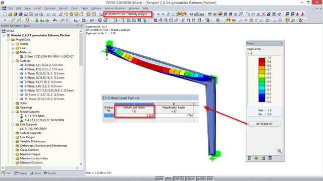
This post verifies the determined mode shapes or critical load factors of the previous beam structures using an FE model in RFEM (surface elements) and RF‑STABILITY.
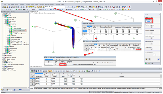
The stability analysis of the steel frame described in my previous post can also be performed in RF‑/FE‑LTB according to the Equivalent Imperfection Method. This post describes how to calculate or determine the critical load factor.

In the following example, the stability analysis of a steel frame can be performed according to the General Method in compliance with EN 1993‑1‑1, Sect. 6.3.4 in the RF‑/STEEL EC3 add-on module. The first of my three posts shows the determination of the critical load factor for design loads required by the design concept, which reaches the elastic critical buckling load with deformations from the main framework plane.