54 Results
View Results:
Sort by:
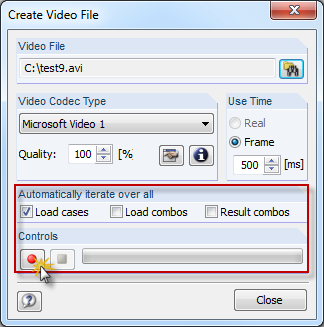
In RFEM and RSTAB, you can now create a video file of the results of all load cases, load combinations, and result combinations. Thus, you can very easily create a visual presentation of a moving load crossing a bridge, for example. This function is available under "Tools" → "Create Video File".

Plate girder is an economical choice for long spans construction. I-section steel plate girder typically has a deep web to maximize its shear capacity and flange separation, yet thin web to minimize the self-weight. Due to its large height-to-thickness (h/tw) ratio, transverse stiffeners may be required to stiffen the slender web.

When calculating regular structures, data input is often not complicated but time-consuming. Input automation can save valuable time. The task described in the present article is to consider the stories of a house as single construction stages. Data is entered using a C# program so that the user does not have to enter the elements of the individual floors manually.

The determined values for the influence ordinates are displayed as decimal numbers with up to six decimal places by default. This is usually sufficient for the influence lines of internal forces.

In January 2015, DIN Committee NA 005‑08‑23 Steel Bridges applied the introduction of a modification in equation 10.5 of DIN EN 1993‑1‑5. This involves the interaction of longitudinal and transverse pressure in a buckling analysis. Now, the interaction equation provides for auxiliary factor V, which is calculated from the reduction factors of the longitudinal and transverse stresses.
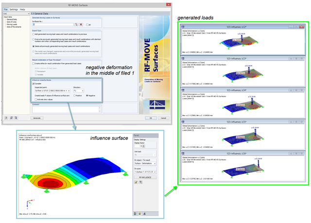
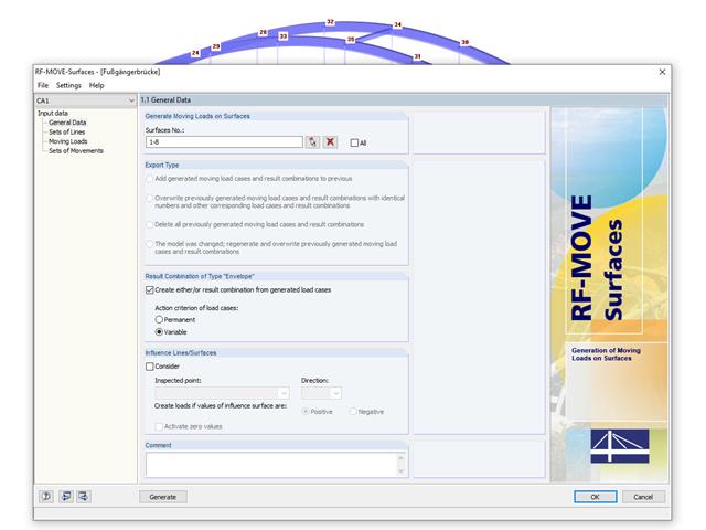
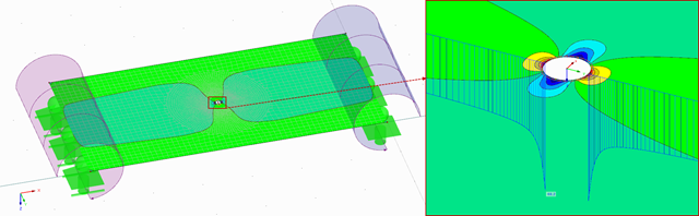
For the reduction of loads generated in RF‑MOVE Surfaces, you can consider the influence surfaces of a selected point. The influence surfaces are determined by RF-INFLUENCE. This procedure is useful in cases where only unfavorably acting loads should be considered. Depending on the unfavorable action, you should select the positive or negative direction.

The additional loads from self‑weight are usually composed of several layers; for example, classic floor and ceiling layers in buildings, or road coatings for bridge constructions. When defining load definitions in RFEM and RSTAB, you can use the multi-layer load to define the individual layers with thickness and specific weight.

With RFEM version 5.06, member stiffnesses can be influenced by methods that are aligned with US steel construction standard ANSI/AISC 360-10. According to this standard, reduction factor τb must be considered for the determination of internal forces in all members of which the flexural resistance contributes to the model's stability. This coefficient depends on the axial force in the member: The larger the axial force, the larger τb is.
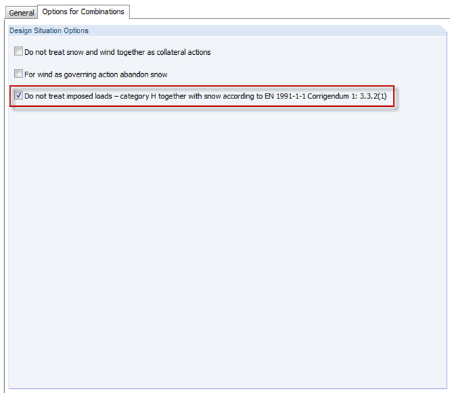
In the H - Roofs category, imposed loads have to be applied. These are usually the technician loads for construction and maintenance. Since there is no maintenance for snow, category H must not include both snow and imposed loads together. You can consider thi in the options for automatic combinations.
This paper is related to an ongoing project for which a structural digital twin of the Kalix bridge in Sweden is being developed and implemented.

Diagonals of double angles are used for pipe bridge construction and for truss girders, among other things. They are usually subjected to tension, but it is necessary to transfer them in smaller compression forces with regard to the load application. In the case of slender diagonals in particular, you should also consider the bending due to self‑weight.

The Construction Stages Analysis (CSA) add-on allows for the design of member, surface, and solid structures in RFEM 6 considering the specific construction stages associated with the construction process. This is important since buildings are not constructed all at once, but by gradually combining individual structural parts. The single steps in which structural elements, as well as loads, are added to the building are called construction stages, whereas the process itself is called a construction process.
Thus, the final state of the structure is available upon completion of the construction process; that is, all the construction stages. For some structures, the influence of the construction process (that is, all the individual construction stages) might be significant and it should be considered so that errors in the calculation are avoided. A general overview of the CSA add-on is given in the Knowledge Base article titled “Consideration of Construction Stages in RFEM 6”.
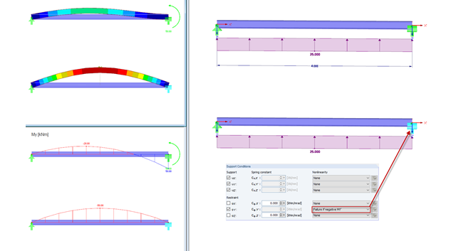
In practice, an engineer often faces the task of representing the support conditions as close to the reality as possible in order to be able to analyze the deformations and internal forces of the structure subjected to their influence and to enable construction that is as cost efficient as possible. RFEM and RSTAB provide numerous options for defining nonlinear nodal supports. This second part describes the options for creating a nonlinear support for a restraint and provides a simple example. For a better understanding, the result is always compared to a linearly defined support.
RF-MOVE Surfaces facilitates the generation of load cases from different positions of moving loads. Based on the load positions of the moving load, the program generates separate load cases for RFEM 5. Optionally, an enveloping result combination of all load positions is created.
With RF-FOUNDATION Pro, it is possible to determine the settlements of single foundations and resulting spring stiffnesses of the nodal supports. These spring stiffnesses can be exported into the RFEM model and used for further analyses.
.png?mw=640&hash=5852c5c8a1cdb9f021a168d75c0a0466fb430ef7)
Lattice towers represent typical applications in steel construction. Examples of this special type of truss structure are antenna and overhead line towers, as well as columns for wind power stations, cable cars, and supporting frame constructions. The modeling can be done individually in RFEM and RSTAB by entering various tower elements. Furthermore, you can use different copy functions and parameterized input options. However, this procedure normally requires considerable effort. It is more convenient to model such structures using prefabricated catalog elements provided by the Block Manager. These elements are automatically stored in the database during program installation. Thus, you can use tower segments, platforms, antenna brackets, cable ducts, and so on as parameterized building blocks for generating diverse tower structures.

The calculation of complex structures by means of finite element analysis software is generally performed on the entire model. However, the construction of such structures is a process carried out in multiple stages where the final state of the building is achieved by combining the separate structural parts. To avoid errors in the calculation of overall models, the influence of the construction process must be considered. In RFEM 6, this is possible using the Construction Stages Analysis (CSA) add-on.

Compliance with building codes, such as Eurocode, is essential to ensure the safety, structural integrity, and sustainability of buildings and structures. Computational Fluid Dynamics (CFD) plays a vital role in this process by simulating fluid behavior, optimizing designs, and helping architects and engineers meet Eurocode requirements related to wind load analysis, natural ventilation, fire safety, and energy efficiency. By integrating CFD into the design process, professionals can create safer, more efficient, and compliant buildings that meet the highest standards of construction and design in Europe.
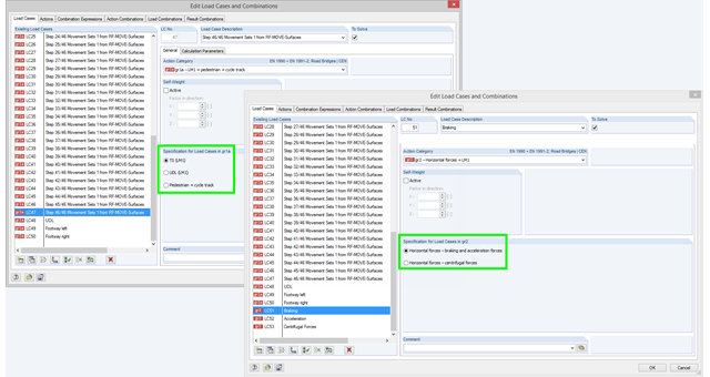
If you select the combinatorics according to EN 1990 + EN 1991‑2 and define a load case in action category gr1a, gr2, or gr5, you have to additionally define in the program which load model should be taken as a basis for the load case. This information is crucial for defining combination rules for automatic combinations according EN 1990 + EN 1991-2. In the gr1a category, you can select TS (LM1), UDL (LM1), or pedestrian and cycle track, for example. TS (LM1) is preset by default. In the gr2 category, you can select breaking and acceleration forces or centrifugal forces as a specification.

A standard scenario in timber member construction is the ability to connect smaller members by means of bearing on a larger girder member. Additionally, member end conditions may include a similar situation where the beam is bearing on a support type. In either scenario, the beam must be designed to consider the bearing capacity perpendicular to the grain according to NDS 2018 Sec. 3.10.2 and CSA O86:19 Clauses 6.5.6 and 7.5.9. In general structural design software, it is typically not possible to carry out this full design check, as the bearing area is unknown. However, in the new generation RFEM 6 and Timber Design add-on, the added 'design supports' feature now allows users to comply with the NDS and CSA bearing perpendicular to the grain design checks.
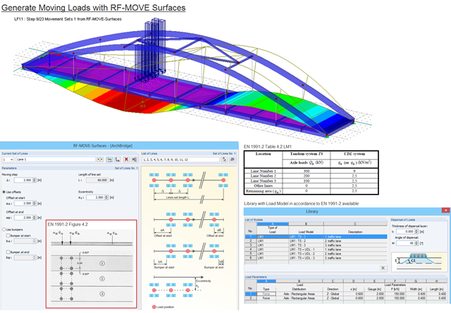
Moving loads can be generated easily with RF‑MOVE Surfaces. A library is available with load models as defined in Eurocode 1, Part 2. The input of step size, offsets at start and end, and the distance to a reference line make it possible for the user to generate user‑defined load models and influence the number of load cases generated. RF‑MOVE Surfaces generates load cases and, optionally, a result combination as an envelope of all results.

The effects due to snow load are described in the American standard ASCE/SEI 7-16 and in Eurocode 1, Parts 1 through 3. These standards are implemented in the new RFEM 6 program and the Snow Load Wizard, which serves to facilitate the application of snow loads. In addition to this, the most recent generation of the program allows the construction site to be specified on a digital map, thus allowing the snow load zone to be imported automatically. These data are, in turn, used by the Load Wizard to simulate the effects due to the snow load.
As mentioned in Part 1, according to the current standard DIN 18008-3, it is allowed in glass construction to represent point supports for glass components by means of FEM in order to design the adequate ultimate limit state. The rules are described in Annex B of the standard [1].
.png?mw=640&hash=44d3f64925841d58547bef5a5e8ff90fab8aceaf)
The American Wood Council (AWC) has released the 2018 Edition of the National Design Specification (NDS) for Wood Construction. This is the second edition of the NDS to contain a chapter dedicated to cross-laminated timber (CLT) design. Therefore, a couple of revisions were included in the 2018 NDS when compared to the previous 2015 Edition.
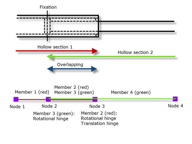
The nested components of a telescopic boom of a construction machine, for example, transport their forces mechanically between the components.

When a concrete slab is set upon the top flange, its effect is like a lateral support (composite construction), preventing problems of torsional buckling stability. If there is a negative distribution of the bending moment, the bottom flange is subjected to compression and the top flange is under tension. If the lateral support given by the stiffness of the web is insufficient, the angle between the bottom flange and the web intersection line is variable in this case so that there is a possibility of distortional buckling for the bottom flange.
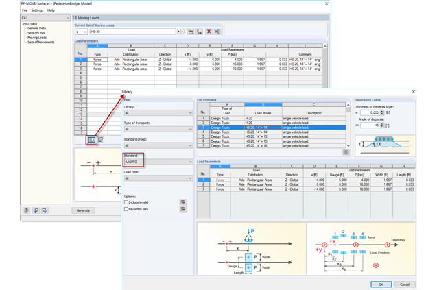
Design loads specified in the AASHTO Bridge Design Specification are available in the RF-MOVE Surfaces moving load library. Design Truck (HS-20), Tandem, Type 3, and Overload are available options.
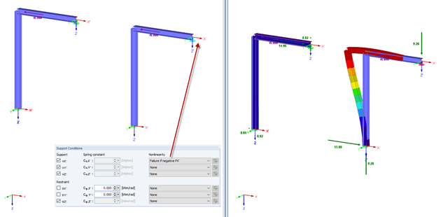
In practice, an engineer often faces the task of representing the support conditions as close to the reality as possible in order to be able to analyze the deformations and internal forces of the structure subjected to their influence, and to enable construction that is as cost-effective as possible. RFEM and RSTAB provide numerous options for defining nonlinear nodal supports. The first section of my article describes the options for creating a nonlinear free support and provides a simple example. For a better understanding, the result is always compared to a linearly defined support.

Imperfections in construction engineering are associated with production-related deviation of structural components from their ideal shape. They are often used in a calculation to determine the equilibrium of forces for structural components on a deformed system.
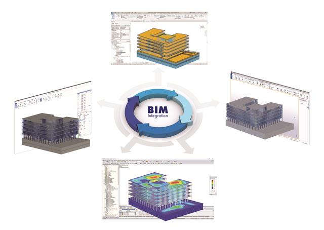
The building and construction industry is increasingly digitized. Structural engineers, a smaller group in the construction industry, are not always considered to be engineers who follow the latest trends immediately. There is often good reason for this. Many consider this to be the reason that topics such as utilizing the BIM method are not yet the standard in structural engineering. However, the past few years have shown that a process of rethinking has begun, and new digital trends are being picked up and applied.