Construction Process
The final state of the construction is achieved by adding structural elements to the structure in subsequent stages. This is called a construction process, and it determines which structural parts are active in each construction stage.
In addition to the self-weight of the individual structural elements that are active in the specific construction stage, the structure or its individual parts may also be subjected to loading due to the environmental conditions and the construction method itself.
Thus, both self-weight and time-limited loads should be considered and implemented in the ground. Furthermore, the loading associated with the structure or its individual parts during the construction process results in deformations that should also be taken into account. Neglecting the influence of the construction process can lead to errors in the calculation of overall models.
Construction Stages Analysis (CSA) Add-on in RFEM 6
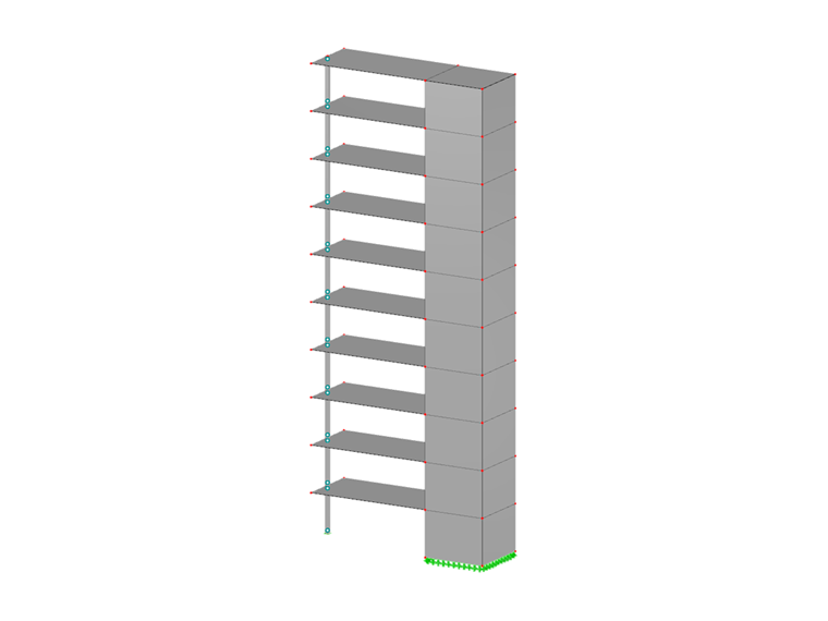
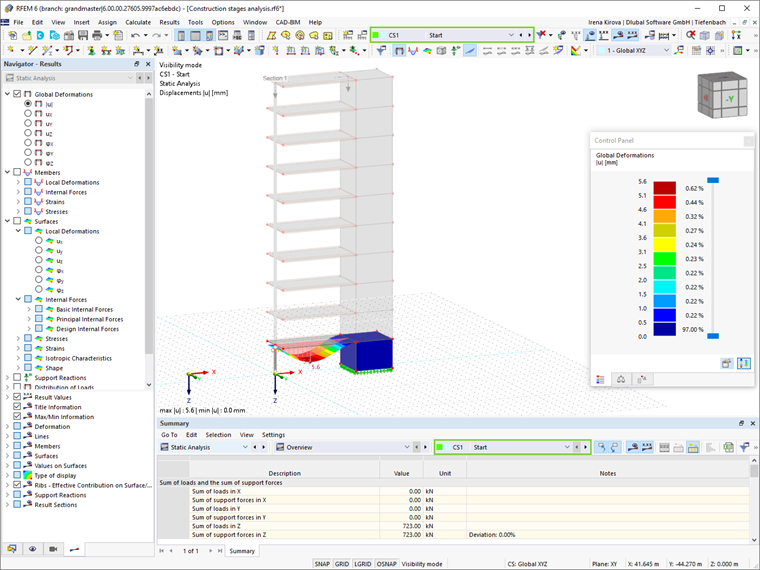
RFEM 6 offers the Construction Stages Analysis (CSA) add-on to consider the construction process of structures (member, surface, and solid structures). It is an excellent tool to display individual construction stages and analyze the structure up to the point of the structural design (Image 1).
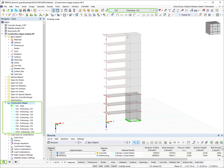
The construction stages can be defined easily by assigning the individual structural components and load cases to the corresponding stages (Image 2). Member, surface, and solid elements, as well as their properties (for example, member and line hinges, degrees of freedom for supports, and so on) can be added, removed, modified, and reactivated.
Hence, structural modifications (such as those that occur when bridge girders are successively grouted or when columns are settled) can easily be modeled in RFEM 6 using the CSA add-on. This add-on also provides the possibility to consider nonlinear effects such as tension member failure and nonlinear supports.
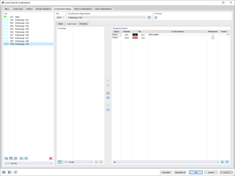
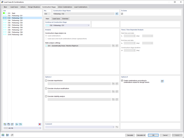
The Construction Stages Analysis add-on allows the user to set specific analysis options as shown in Image 3. By means of combinatorics, permanent and non-permanent loads can be superimposed in load combinations. For instance, it is possible to determine the maximum internal forces of different crane positions or to consider temporary mounting loads available in only one construction stage.
The calculation is based on the comparison between the resulting geometry differences of the ideal system and the structural system deformed due to the previous construction stage. In this manner, the succeeding construction stage is based on the structural system associated with the previous construction stage.
Results
Finally, results in terms of individual construction stages are available both numerically and graphically (Image 4). The construction stages can be considered in the combinatorics and included in the design as well. In addition, all structural and load data for each construction stage can be documented and exported in the printout report.
Final Remarks
The Construction Stages Analysis (CSA) add-on is offered in RFEM 6 to account for the construction process of structures (that is, to display individual construction stages and analyze the structure up to the point of the structural design).
Structural components as well as load cases can be assigned easily to the corresponding stage. In fact, structural modifications can be modeled by adding, removing, modifying, and reactivating both elements and their properties.
The possibility to create automatic and manual combinatorics with load combinations in the individual construction stages allows the consideration of mounting loads, mounting cranes, and so on. The add-on also allows the consideration of nonlinear effects (for example, nonlinear supports, tension member failure, and so on), as well as interaction with other add-ons.
The results of the individual construction stages can be displayed in both graphical and tabular form and can be exported in the printout report. The construction stages can be considered in the combinatorics and can be further included in the design.