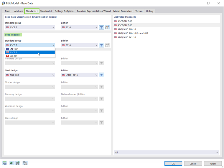
Activation of Standards
In RFEM 6, snow loads can be applied to the model according to different standards. The preferred standard for the Load Wizards can be selected in the Standards I tab of the model’s Base Data. As Image 1 shows, the snow load can be generated according to ASCE 7, EN 1991, or the SIA 261 standard groups and their associated editions/national annexes.
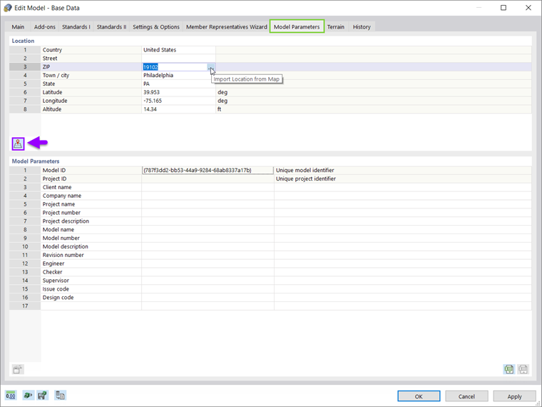
Import of Construction Site for Snow Load Determination
The basis for calculating a snow load is the snow load zone where the structure is located. To determine the snow load zone as well as the characteristic value of the snow load, it is necessary to set the location of the model in the Model Parameters tab of the Base Data (Image 2).
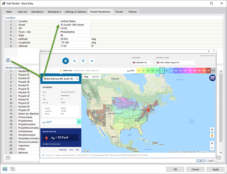
The model’s location can also be imported directly from a digital map, as shown in Image 3. Hence, in addition to the address data (including altitude), the snow load zone is imported automatically and the relevant data are, in turn, used by the Load Wizard to simulate the effects due to the snow load.
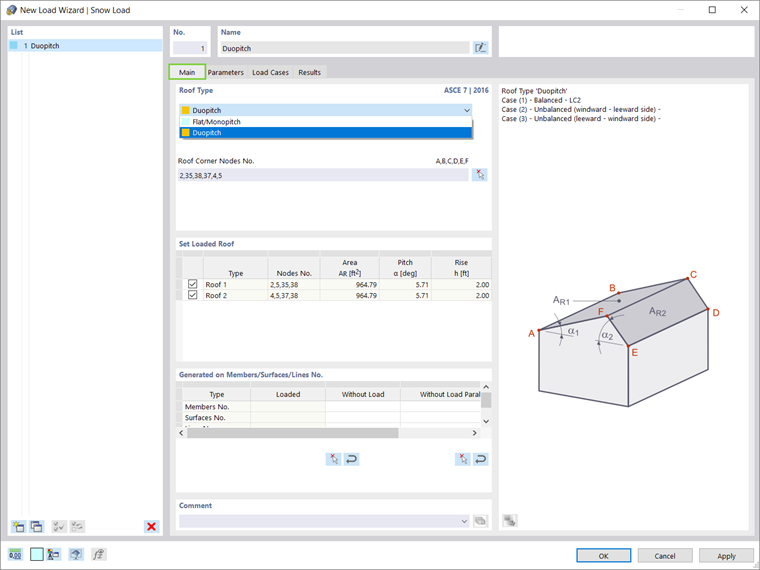
Load Wizards – Snow Loads
Load Wizards in RFEM 6 facilitate the input of member and surface loads by converting area loads to member loads as well as applying snow and wind loads to surfaces and members. They can be expanded in the Data navigator as shown in Image 4.
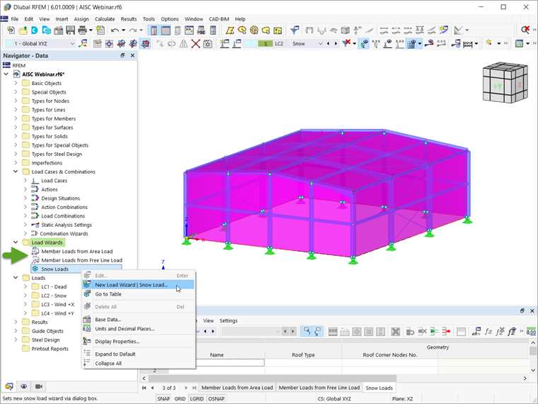
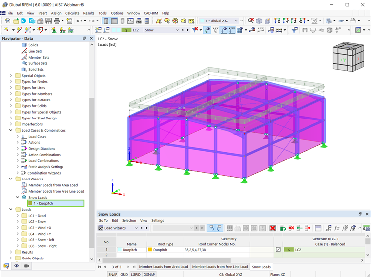
The Snow Load Wizard assists with the generation of snow load effects on flat/monopitch and duopitch roofs according to the selected standard. Once the roof geometry is defined by selecting the roof corner nodes, the program automatically lists the surfaces, members, and lines on which the load has been generated (Image 5). For duopitch roofs, it is also possible to set the loaded roof plane.
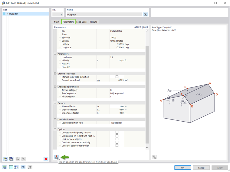
The relevant parameters for determining the snow load effects are also listed in the Parameters tab of the Load Wizard window (Image 6). Options such as consideration of member eccentricities and section distribution can also be activated in this tab. If the location parameters of the model have not been defined beforehand, both the location and the load parameters can be imported from the Snow Load Map through the related icon.
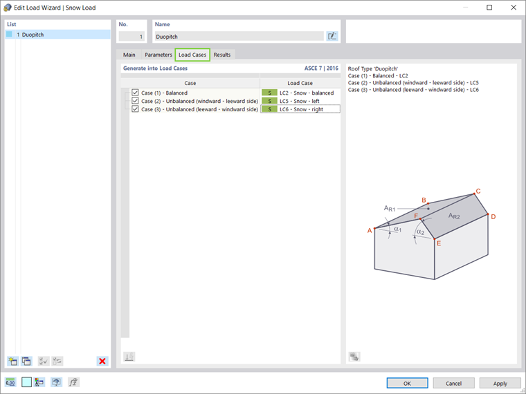
The Load Cases tab of the same window allows the generation of snow loads into existing or new load cases. In Image 7, the snow load is applied according to the ASCE 7 standard and therefore, the program suggests three default load cases: one for the balanced snow load (applied on both roof planes) and two for individual loading on each roof plane.
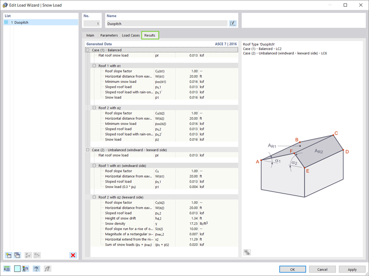
Finally, the generated data are listed in the Results tab of the Load Wizard window. The data are available separately for each load case. When working with the ASCE 7 standard, these data include the flat roof snow, the roof slope factor, and the sloped roof load that defines the final value of the snow load (Image 8). In the case of an unbalanced snow load, the final snow load value on the windward roof plane is 30 percent of the sloped roof load. The snow load value on the leeward roof plane is calculated as the sum of the sloped roof load and the magnitude of a rectangular surcharge.
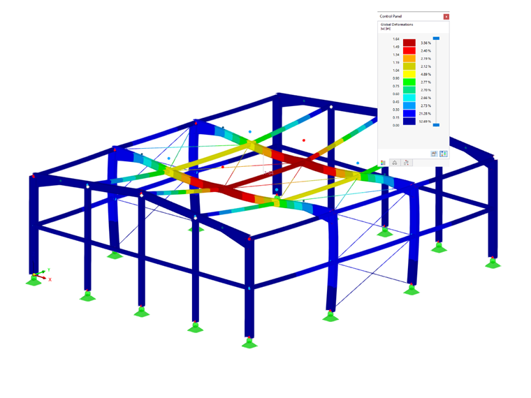
The snow load generated by the Snow Load Wizard is shown in Image 9.
Final Remarks
Load Wizards facilitate the input of member and surface loads by providing the option to convert area loads to member loads as well as to apply snow load and wind loads in a fast and straightforward manner. Thus, the snow load can be applied to flat/monopitch and duopitch roofs using the Snow Load Wizard accessible via the Data navigator or via "Insert → Load Wizards → Snow Load".
In RFEM 6, the Load Wizards are connected to the Geo-Zone Tool and therefore, the model's location as well as the load parameters can be imported directly from a digitized Snow Load Map. Then, only the geometry of the roof itself needs to be defined in the Load Wizard, which will automatically generate the snow loads based on the selected standard. The Load Wizard is also capable of generating and placing snow loads into already existing load cases and can provide the generated data needed for determining the snow load effects.