
- Design of five types of seismic force-resisting systems (SFRS) includes Special Moment Frame (SMF), Intermediate Moment Frame (IMF), Ordinary Moment Frame (OMF), Ordinary Concentrically Braced Frame (OCBF), and Special Concentrically Braced Frame (SCBF)
- Ductility check of the width-to thickness ratios for webs and flanges
- Calculation of the required strength and stiffness for stability bracing of beams
- Calculation of the maximum spacing for stability bracing of beams
- Calculation of the required strength at hinge locations for stability bracing of beams
- Calculation of the column required strength with the option to neglect all bending moments, shear, and torsion for overstrength limit state
- Design check of column and brace slenderness ratios
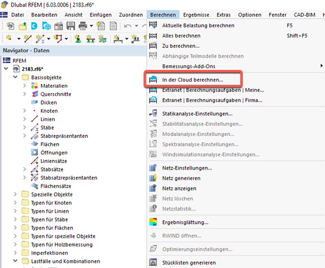
- Outsource calculation on a computing server in the cloud
- Option to select different powerful computing servers
- Clearly arranged display of all calculation tasks in the Extranet
- Calculated files are available for download for two months
- Virtually unlimited computing capacity using cloud technology

Did you know? In the Design Supports, you can now define fully threaded screws as transversal compression stiffening elements for the "Compression Perpendicular to Grain" design. In this case, the pressing-in and buckling of the bolts is analyzed.
Moreover, the design shear resistance is checked in the plane of the screw tip. The angle of dispersal can be considered as linear under 45° or nonlinear (according to Bejtka, I. (2005). Verstärkung von Bauteilen aus holz mit vollgewindeschrauben. KIT Scientific Publishing.).

Do you already know the editor for mesh refinement control? It is a great help for your work! Why? It's easy – it gives you the following options:
- Graphic visualization of the areas with mesh refinements
- Mesh refinement of zones
- Deactivating the standard 3D solid mesh refinement with transversion into the corresponding manual 3D mesh refinements.
These options help you to formulate a suitable rule for meshing the entire model, even for the models with unusual dimensions. Use the editor to efficiently define small model details on large buildings or detailed meshing areas in the coating area of the model. You will be amazed!
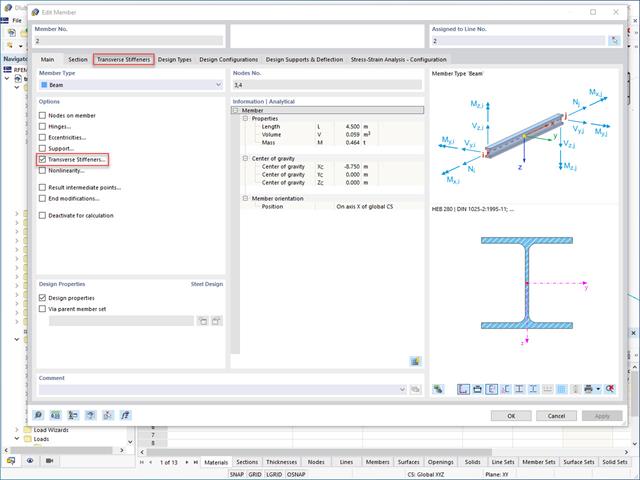
Do you want to generate surfaces from members? Nothing is easier than that. You can find the right solution under Transverse Stiffeners Options when processing the members. In this case, you can adjust the transverse stiffeners according to the type and position.

The program does a lot of work for you. For example, the load or result combinations required for the serviceability limit state are generated and calculated in RFEM/RSTAB. You can select these design situations for the deflection analysis in the Aluminum Design add-on. Depending on the specified precamber and reference system, the program determines the deformation values at each location of a member. They are then compared to the limit values.
You can specify the deformation limit value individually for each structural component in Serviceability Configuration. In this case, you define the maximum deformation depending on the reference length as the allowable limit value. By defining design supports, you can segment the components. In this way, you can determine the corresponding reference length automatically for each design direction.
And that's not all. Based on the position of the assigned design supports, the program allows you to automatically determine the distinction between beams and cantilevers. The limit value is thus determined accordingly.

In the "Deflection and Design Support" tab under "Edit Member", the members can be clearly segmented using optimized input windows. Depending on the supports, the deformation limits for cantilever beams or single-span beams are used automatically.
By defining the design support in the corresponding direction at the member start, member end, and intermediate nodes, the program automatically recognizes the segments and segment lengths to which the allowable deformation is related. It also automatically detects whether it is a beam or a cantilever due to the defined design supports. The manual assignment, as in the previous versions (RFEM 5), is no longer necessary.
The "User-Defined Lengths" option allows you to modify the reference lengths in the table. The corresponding segment length is always used by default. If the reference length deviates from the segment length (for example, in the case of curved members), it can be adjusted.
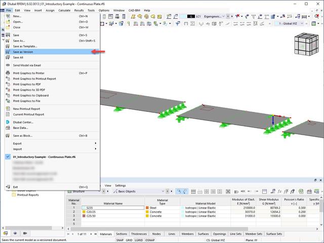
It is possible to save different model versions within a model by using the Save as Version function. In the Base Data of the model, the different model versions can be displayed in the History tab.

In addition to other predefined components in the design add-on for steel connections, the universal base component "General Weld" can be used to enter complex connection situations.

The object types listed below can be graphically assigned to the elements of the structure modeled in the program.
- Nodal supports
- Member shear panels
- Local reductions of member cross-sections
- Member transverse stiffeners
- Member longitudinal welds
- Effective lengths
- Boundary conditions
- Line supports
- Loads
- Member support
- Punching reinforcements
- Mesh refinements
- Surface reinforcements
- Surface results adjustments
- Surface support
- Service classes
- Imperfections

Your options in timber design are diverse. You can consider cut-to-grain angles, transverse tension stresses, and volume-dependent radii of curvature for tapered and curved members. To design the area of the grain cut, the strength is adjusted accordingly in the case of bending tension or bending pressure. In order to also allow you to perform a stability analysis with the equivalent member method, the height to determine the effective and lateral-torsional buckling lengths is set at a distance of 0.65 × h to the actual design point.

Your RFEM/RSTAB program is responsible for generating and calculating the load and result combinations required for the serviceability limit state. Select the design situations for the deflection analysis in the Timber Design add-on. The calculated deformation values are then determined at each location of a member, depending on the specified precamber and the reference system, and then compared to the limit values.
You can specify the deformation limit value individually for each structural component in Serviceability Configuration. In this case, the maximum deformation should not exceed the permissible limit value, depending on the reference length. When defining design supports, you can segment the components. This allows you to determine the corresponding reference length automatically for each design direction.
Based on the position of the assigned design supports, the program automatically determines the difference between beams and cantilevers. Thus, you can be sure that the limit value is determined accordingly.

In RFEM/RSTAB, you have the option to generate and then calculate the load or result combinations required for the serviceability limit state. You can select these design situations for the deflection analysis in the Steel Design add-on. The calculated deformation values are determined accordingly at each location of a member, depending on the specified precamber and reference system. Finaly, you can compare these deformation values with the limit values.
Did you know? You can specify the deformation limit value individually for each structural component in Serviceability Configuration. Define the maximum deformation depending on the reference length as the allowable limit value. By defining design supports, you can segment the components in order to determine the corresponding reference length automatically for each design direction.
Based on the position of the assigned design supports, the distinction between beams and cantilevers is made automatically so the limit value can be determined accordingly.

Did you know? In contrast to other material models, the stress-strain diagram for this material model is not antimetric to the origin. You can use this material model to simulate the behavior of steel fiber-reinforced concrete, for example. Find detailed information about modeling steel fiber-reinforced concrete in the technical article about Determining the material properties of steel-fiber-reinforced concrete.
In this material model, the isotropic stiffness is reduced with a scalar damage parameter. This damage parameter is determined from the stress curve defined in the Diagram. The direction of the principal stresses is not taken into account. Rather, the damage occurs in the direction of the equivalent strain, which also covers the third direction perpendicular to the plane. The tension and compression area of the stress tensor is treated separately. In this case, different damage parameters apply.
The "Reference element size" controls how the strain in the crack area is scaled to the length of the element. With the default value zero, no scaling is performed. Thus, the material behavior of the steel fiber concrete is modeled realistically.
Find more information about the theoretical background of the "Isotropic Damage" material model in the technical article describing the Nonlinear Material Model Damage.

- Many predefined components: Allow easy input of typical connection situations, such as end plates, angles, multi-wall sheets, cleats, fin plates
- Universally applicable basic components (plates, welds, bolts, auxiliary planes) for entering complex connection situations
- Graphical display of the connection geometry that is updated in parallel with the input
- The Steel Joints Template included in the add-on allows you to select from several connection types and, and once selected, it will be applied to your model.
- Wide range of cross-section shapes: Includes I-sections, channel sections, angles, T-sections, built-up cross-sections, RHS (rectangular hollow sections), and thin-walled sections
- The Template covers connections from three general categories: Rigid, Pinned, Truss
- Automatic adaptation of the connection geometry, even if the structural components are subsequently edited, based on the relative relation of the components
One thing is absolutely undisputed: WebService and API covers universal aspects in the construction industry. However, there is an issue. For the calculation and design, you need different features for each region, country, company, and civil engineer. Everyone has their own requirements. We have solved this problem. Since with WebService and API, you can easily create your very own calculation and design system. Always at your side: The performance and reliability of RFEM, RSTAB, and RSECTION.
The need for adapted and automated structural analysis and design is constantly increasing. WebService technology allows you to create special functionalities quickly and precisely. Our customers can develop such solutions independently or in cooperation with us. See for yourself and give it a try!

The stand-alone program RWIND 2 takes care of fresh air. It is used for the numerical simulation of wind flow and is available in a Basic as well as a Pro version. What additional features does RWIND Pro offer you? It allows for the calculation of transient incompressible turbulent wind flows (in addition to the stationary ones in RWIND Basic). But that's not all. Intrested to learn more? Find out more here:
Do you have to calculate multiple load combinations in your models? Then several solvers (one per core) are initiated in parallel, each of which calculates a load combination. This ensures a better utilization of the cores and thus faster calculations.
Go to Explanatory Video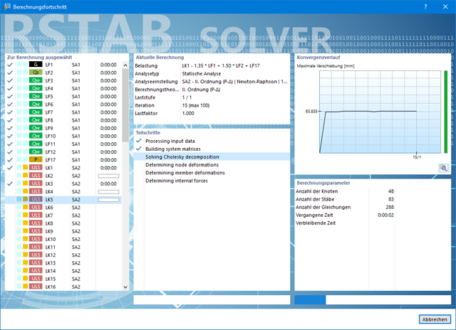
Also in this case, RSTAB will certainly convince you. With the powerful calculation kernel, its optimized networking and support of multi-core processor technology, the Dlubal structural analysis program is far ahead. This allows you to calculate more linear load cases and load combinations using several processors in parallel without using additional memory. The stiffness matrix only has to be created once. Thus, it is possible for you to calculate even large systems with the fast and direct solver.
Do you have to calculate multiple load combinations in your models? The program initiates several solvers in parallel (one per core). Each solver then calculates a load combination for you. This leads to better utilization of the cores.
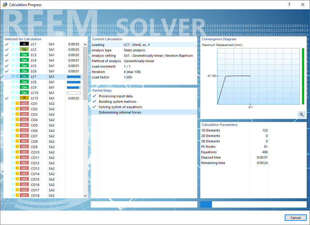
You can systematically follow the development of the deformation displayed in a diagram during the calculation, and thus precisely evaluate the convergence behavior.

Don't have an RFEM or RSTAB license yet? No problem. Just download the 90-day trial version. This will allow you to test the full version of the program without any limitations.
Download Trial Versions
The Concrete Design add-on combines all CONCRETE add-on modules from RFEM 5 / RSTAB 8. Compared to these add-on modules, the following new features have been added to the Concrete Design add-on for RFEM 6 / RSTAB 9:
- Input of design-relevant specifications (effective lengths, durability, reinforcement directions, surface reinforcement) directly in the RFEM or RSTAB model
- Extensive input options for longitudinal and transverse reinforcement of members
- Detailed intermediate results for the design with specification of the equations of the applied standard for better traceability of the calculation
- New interaction diagram with interactive graphic for N, M, and M + N from cross-section design incl. output of the secant and tangent stiffness
- Design of the defined reinforcement in the ultimate limit state and serviceability limit state incl. graphical output of the design ratio for the respective component
- Automatic check of the defined reinforcement with regard to the construction or general reinforcement rules for reinforced member and surface components
- Cross-section design optionally with net values of the concrete section
- Design according to the Russian standard SP 63.13330

Compared to the RF‑/STEEL EC3 add-on module (RFEM 5 / RSTAB 8), the following new features have been added to the Steel Design add-on for RFEM 6 / RSTAB 9:
- In addition to Eurocode 3, other international standards are integrated (such as AISC 360, CSA S16, GB 50017, SP 16.13330)
- Consideration of hot-dip galvanizing (DASt guideline 027) in the fire protection design according to EN 1993‑1‑2
- Input option for transverse stiffeners that can be taken into account in the shear buckling analysis
- Lateral-torsional buckling can also be checked for hollow sections (for example, relevant for slender, high rectangular hollow sections)
- Automatic detection of members or member sets valid for the design (for example, automatic deactivation of members with invalid material or members already contained in a member set)
- Design settings can be adjusted individually for each member
- Graphical display of the results in the gross section or the effective section
- Output of the used design check formulas (including a reference to the used equation from the standard)

The form-finding process gives you a structural model with active forces in the "prestress load case" This load case shows the displacement from the initial input position to the form-found geometry in the deformation results. In the force or stress-based results (member and surface internal forces, solid stresses, gas pressures, and so on), it clarifies the state for maintaining the found form. For the analysis of the shape geometry, the program offers you a two-dimensional contour line plot with the output of the absolute height and an inclination plot for the visualization of the slope situation.
Now, a further calculation and structural analysis of the entire model is performed. For this purpose, the program transfers the form-found geometry including the element-wise strains into a universally applicable initial state. You can now use it in the load cases and load combinations.

- Selection of nodes in the RFEM model, automatic recognition and assignment of the members connected to the node
- Many predefined components available for easy input of typical connection situations (for example, end plates, cleats, fin plates)
- Universally applicable basic components (plates, welds, auxiliary planes) for entering complex connection situations
- No manual editing of the FE model required by the user, the essential calculation settings can be changed via the configuration settings
- Automatic adaptation of the connection geometry, even if the members are subsequently edited, due to the relative relation of the components to each other
- Parallel to the input, a plausibility check is carried out by the program to quickly detect missing input or collisions, for example
- Graphical display of the connection geometry that is updated in parallel with the input

You can display all essential results on the FE model. In this case, you can filter the results separately according to the respective components.
Furthemore, RFEM delivers you all design checks in a tabular form, including the display of the formulas used. If you wish, you can transfer the result tables to the RFEM printout report.

In the modal analysis settings, you have to enter all data that are necessary for the determination of the natural frequencies. These are, for example, mass shapes and eigenvalue solvers.
The Modal Analysis add-on determines the lowest eigenvalues of the structure. Either you adjust the number of eigenvalues or let them determined automatically. Thus, you should reach either effective modal mass factors or maximum natural frequencies. Masses are imported directly from load cases and load combinations. In this case, you have the option to consider the total mass, load components in the global Z-direction, or only the load component in the direction of gravity.
You can manually define additional masses at nodes, lines, members, or surfaces. Furthermore, you can influence the stiffness matrix by importing axial forces or stiffness modifications of a load case or load combination.

In RFEM, you can use these three powerful eigenvalue solvers:
- Root of Characteristic Polynomial
- Method by Lanczos
- Subspace Iteration
RSTAB, on the other hand, provides you with these two eigenvalue solvers:
- Subspace Iteration
- Shifted inverse power method
The selection of the eigenvalue solver depends primarily on your model size.

- Design of tension, compression, bending, shear, torsion, and combined internal forces
- Tension design with consideration of a reduced section area (for example, hole weakening)
- Automatic classification of cross-sections to check local buckling
- Internal forces from the calculation with Torsional Warping (7 DOF) are taken into account by means of the equivalent stress check (currently not for the design standards AISC 360‑16 and GB 50017).
- Design of cross-sections of Class 4 with effective cross-section properties according to EN 1993‑1‑3 (licenses for RSECTION and Effective Sections are required for the RSECTION cross-sections)
- Shear buckling check according to EN 1993‑1‑5 with consideration of transverse stiffeners
- Design of stainless steel components according to EN 1993‑1‑4

- Design of tension, compression, bending, shear, torsion, and combined internal forces
- Tension design with consideration of a reduced section area (for example, hole weakening)
- Automatic classification of cross-sections to check local buckling
- Internal forces from the calculation with Torsional Warping (7 DOF) are taken into account by means of the equivalent stress check (currently not yet for the design standard ADM 2020).
- Design of cross-sections of Class 4 with effective cross-section properties according to EN 1993‑1‑5 (licenses for RSECTION and Effective Sections are required for the RSECTION cross-sections)
- Shear buckling check with consideration of transverse stiffeners

- Calculation of models consisting of member, shell, and solid elements
- Nonlinear stability analysis
- Optional consideration of axial forces from initial prestress
- Four equation solvers for an efficient calculation of various structural models
- Optional consideration of stiffness modifications in RFEM/RSTAB
- Determination of a stability mode greater than the user-defined load increment factor (Shift method)
- Optional determination of the mode shapes of unstable models (to identify the cause of instability)
- Visualization of the stability mode
- Basis for determining imperfection