
The parameters of the National Annexes (NA) to Eurocode 3 of the following countries are integrated:
-
 DIN EN 1993-1-1/NA:2016-04 (Germany)
 -
 ÖNORM EN 1993-1-1/NA:2015-12 (Austria)
 -
 SN EN 1993-1-1/NA:2016-07 (Switzerland)
 -
 BDS EN 1993-1-1/NA:2015-10 (Bulgaria)
 -
 BS EN 1993-1-1/NA:2016-07 (United Kingdom)
 -
 CEN EN 1993-1-1/2015-06 (European Union)
 -
 CYS EN 1993-1-1/NA:2015-07 (Cyprus)
 -
 CSN EN 1993-1-1/NA:2016-06 (Czech Republic)
 -
 DS EN 1993-1-1/NA:2015-07 (Denmark)
 -
 ELOT EN 1993-1-1/NA:2017-01 (Greece)
 -
 EVS EN 1993-1-1/NA:2015-08 (Estonia)
 -
 HRN EN 1993-1-1/NA:2016-03 (Croatia)
 -
 I S. EN 1993-1-1/NA:2016-03 (Ireland)
 -
 ILNAS EN 1993-1-1/NA:2015-06 (Luxembourg)
 -
 IST EN 1993-1-1/NA:2015-11 (Iceland)
 -
 LST EN 1993-1-1/NA:2017-01 (Lithuania)
 -
 LVS EN 1993-1-1/NA:2015-10 (Latvia)
 -
 MS EN 1993-1-1/NA:2010-01 (Malaysia)
 -
 MSZ EN 1993-1-1/NA:2015-11 (Hungary)
 -
 NBN EN 1993-1-1/NA:2015-07 (Belgium)
 -
 NEN EN 1993-1-1/NA:2016-12 (Netherlands)
 -
 NF EN 1993-1-1/NA:2016-02 (France)
 -
 NP EN 1993-1-1/NA:2009-03 (Portugal)
 -
 NS EN 1993-1-1/NA:2015-09 (Norway)
 -
 PN EN 1993-1-1/NA:2015-08 (Poland)
 -
 SFS EN 1993-1-1/NA:2015-08 (Finland)
 -
 SIST EN 1993-1-1/NA:2016-09 (Slovenia)
 -
 SR EN 1993-1-1/NA:2016-04 (Romania)
 -
 SS EN 1993-1-1/NA:2019-05 (Singapore)
 -
 SS EN 1993-1-1/NA:2015-06 (Sweden)
 -
 STN EN 1993-1-1/NA:2015-10 (Slovakia)
 -
 TKP EN 1993-1-1/NA:2015-04 (Belarus)
 -
 UNE EN 1993-1-1/NA:2016-02 (Spain)
 -
 UNI EN 1993-1-1/NA:2015-08 (Italy)
_(1).png?mw=640&hash=415f7bbaf70e41679bb0106e1cf91eaa8c493ec9)
- Automatic generation of FE analysis models: The add-on automatically creates a finite element model (FE) of the steel connection in the background.
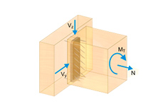
- Consideration of all internal forces: The calculation and design checks include all internal forces (N, Vy, Vz, My, Mz, MT) and are not limited to planar loading.
- Automatic load transfer: All load combinations are automatically transferred to the FE analysis model of the connection. The loads are transferred directly from RFEM, so manual data input is not necessary.
- Efficient modeling: The add-on saves you time when modeling complex connection situations. You can also save the created FE analysis model and use it further for your own detailed analyses.
- Extensible library: An extensive and extensible library with predefined steel connection templates is available.
- Wide applicability: The add-on is suitable for connections of any type and shape, compatible with almost all rolled, welded, built-up, and thin-walled cross-sections.
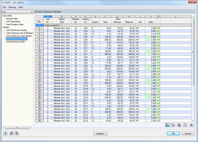
First, the governing design checks of the connection for the respective load case, and load combination, or result combination are displayed. In addition, it is possible to display results separately for sets of members, surfaces, cross-section, members, nodes, and nodal supports.
- You can use a filter to further reduce the displayed results and thus present them in a clearer way.
- Design of member ends, members, nodal supports, nodes, and surfaces
- Consideration of specified design areas
- Check of cross-section dimensions
- Design according to EN 1995-1-1 (European Timber Standard) with the respective National Annexes + DIN 1052 + DSTV DIN EN 1993-1-8 + ANSI / AWC - NDS 2015 (US Standard)
- Design of various materials, such as steel, concrete, and others
- No necessary linking to specific standards
- Extensible library including timber fasteners (SIHGA, Sherpa, WÜRTH, Simpson StrongTie, KNAPP, PITZL) and steel fasteners (standardized connections in steel building design according to EC 3, M-connect, PFEIFER, TG-Technik)
- Ultimate load capacities of timber beams by the companies STEICO and Metsä Wood available in the library
- Connection to MS Excel
- Optimization of connecting elements (the most utilized element is calculated)
.png?mw=640&hash=c9c52de2eed98a2905a02fbf54b073f645c0df2c)
- Design of moment resistant and simple joints of I-shaped rolled cross-sections according to Eurocode 3:
- Moment-resisting end plate connections (type IH/IM)
- Moment resistant purlin splices (PM type)
- Simple joints with angle cleat and long angles (IW and IG types)
- Simple joints with header end plates mounted either on web only or on web and flange (IS type)
- Check of coped connections (IK) in combination with pinned end plates (IS) and angle connections (IW)
- Automatic design of required joint with bolt sizes (all types)
- Check of required thickness of load-bearing members for shear connections
- Results of all required structural details such as appliances, hole arrangements, necessary extensions, a number of bolts, end plate dimensions, and welds
- Results including stiffnesses Sj,ini of bending-resistant connections
- Documentation of available loading and comparison with resistances
- Results of design ratio for each individual joint
- Automatic determination of governing internal forces for several load cases and connection nodes
- Integration in RFEM/RSTAB with automatic geometry recognition and transfer of internal forces
- Optional manual definition of connections
- Extensive library of hollow sections for chords and struts:
- Round sections
- Square sections
- Rectangular sections
- Implemented steel grades: S 235, S 275, S 355, S 420, S 450, and S 460
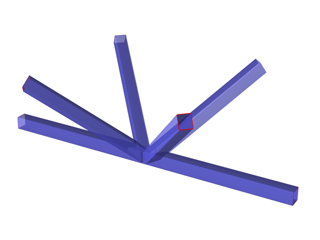
- Various types of connections available, depending on the standard specifications:
- K connection (gap/overlapping)
- KK connection (spatial)
- N connection (gap/overlapping)
- KT connection (gap/overlapping)
- DK connection (gap/overlapping)
- T connection (planar)
- TT connection (spatial)
- Y connection (planar)
- X connection (planar)
- XX connection (spatial)
- Selection of partial safety factors according to the National Annex for Germany, Austria, Czech Republic, Slovakia, Poland, Slovenia, Switzerland, or Denmark
- Adjustable angles between struts and chords
- Optional chord rotation of 90° for rectangular hollow sections
- Consideration of gaps between struts or overlapping struts
- Optional consideration of additional nodal forces
- Design of the connection as the maximum load-bearing capacity of the struts of a truss for axial forces and bending moments
- Applicable for members defined as sets of members
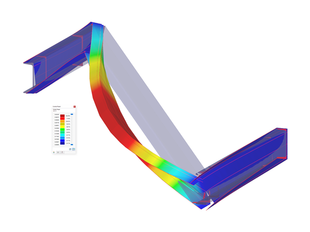
- Separate solver that considers 7 deformation directions (ux, uy, uz, φx, φy, φz, ω) or 8 internal forces (N, Vu, Vv, Mt,pri, Mt,sec, Mu, Mv, Mω)
- Nonlinear design according to second-order analysis
- Input of imperfections
- Calculation of critical load factors and buckling mode shapes as well as the visualization of them (incl. warping)
- Integration into member design in the RF-/STEEL AISC and RF‑/STEEL EC3 add‑on modules
- Available for all thin‑walled steel cross‑sections
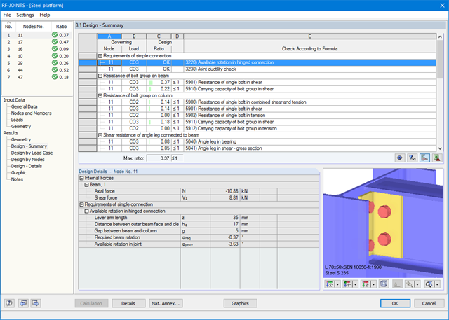
The result windows list all results of the calculation in detail. In addition, 3D graphics are created, where individual components as well as dimension lines and, for example, This allows you, for example, to display or hide the weld data. The summary shows if the individual designs have been fulfilled: The design ratio is additionally visualized with a green data bar, which turns red when the design is not fulfilled. Furthermore, the node number and the governing LC/CO/RC are displayed.
When selecting a design, the module shows the detailed intermediate results including the actions and the additional internal forces from the connection geometry. There is the option to display the results by load case and by node. The connections are represented in a realistic 3D rendering possible to scale. In addition to the main views, it is possible to show the graphics from any perspective.
You can add the graphics with dimensions and labels to the RFEM/RSTAB printout or export them as DXF. The printout report includes all input and result data prepared for test engineers. It is possible to export all tables to MS Excel or in a CSV file. A special transfer menu defines all specifications required for the export.
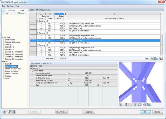
After the calculation, RF-/JOINTS Steel - Column Base displays the following design results:
- Net section design
- Bearing resistance design
- Shear
- Block shear resistance
- Sliding
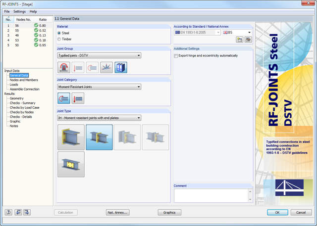
After opening the add-on module, it is necessary to select the joint type (moment resistant or pinned I-beam connection). You can select the individual nodes graphically in the RFEM/RSTAB model.
The RF-/JOINTS Steel - DSTV add-on module recognizes the cross-section including the corresponding material automatically, and checks if a joint design according to the DSTV guideline is possible. Furthermore, you can model and design structurally similar connections on several locations in the beam structure.