- Design of member ends, members, nodal supports, nodes, and surfaces
- Consideration of specified design areas
- Check of cross-section dimensions
- Design according to EN 1995-1-1 (European Timber Standard) with the respective National Annexes + DIN 1052 + DSTV DIN EN 1993-1-8 + ANSI / AWC - NDS 2015 (US Standard)
- Design of various materials, such as steel, concrete, and others
- No necessary linking to specific standards
- Extensible library including timber fasteners (SIHGA, Sherpa, WÜRTH, Simpson StrongTie, KNAPP, PITZL) and steel fasteners (standardized connections in steel building design according to EC 3, M-connect, PFEIFER, TG-Technik)
- Ultimate load capacities of timber beams by the companies STEICO and Metsä Wood available in the library
- Connection to MS Excel
- Optimization of connecting elements (the most utilized element is calculated)
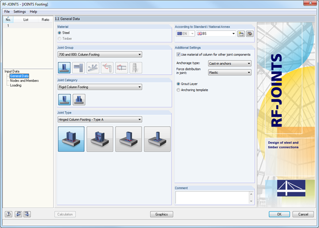
The Hinged Column Footing category provides four different base plate connections:
- Simple column base
- Tapered column base
- Column base for rectangular hollow sections
- Column base for circular hollow sections
The Restraint Column Footing category provides five different joint layouts of I-sections:
- Base plate without stiffening
- Base plate with stiffeners in center of flanges
- Base plate with stiffeners on both sides of column
- Base plate with channel sections
- Pocket foundation
All connection types include a base plate welded around a steel column. Connections with anchors are set in concrete within the foundation. You can select anchor types M12 – M42 with steel grades of 4.6 – 10.9. The top and bottom sides of the anchors can be provided with round or angled sheets for better load distribution or anchorage. In addition, you can use rectangular or circular anchor heads with threads applied at the member ends.
The material and thickness of the grout layer, as well as the dimensions and material of the footing, can be set freely. Furthermore, you can define edge reinforcement of the footing. For a better transfer of shear forces, it is possible to arrange a shear key (cleat) on the bottom side of the base plate.
Shear forces are transferred by a cleat, anchors, or friction. You can combine the individual components.
After the calculation, RF-/JOINTS Steel - Column Base displays the following design results:
- Net section design
- Bearing resistance design
- Shear
- Block shear resistance
- Sliding
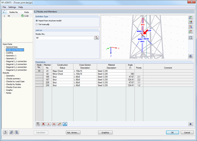
After you have selected the joint type, the connection category, and the design standard in the first input window, you can define the node to be imported from RFEM/RSTAB and to be used for the design of the joint in Window 1.2. Optionally, you can define the connection geometry manually.
In the other input windows, you can then define the parameters of the connection, such as The loading is imported from RFEM/RSTAB or, in the case of manual joint definition, loads are entered.
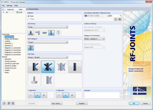
- Wide range of joint types, for example:
- Bolted connection of diagonals without gusset plate 2D
- Bolted connection of diagonals without gusset plate 3D
- Bolted column joint
- T-, K-, and KT-joints considered for connections of diagonals
- Various categories of connections:
- A - shear/hole bearing connection
- B - slip-resistant connection at serviceability limit state
- C - slip-resistant connection at ultimate limit state
- Bolt strength classes of 4.6 - 10.9
- Bolt diameters M12 - M42
- Modifiable bolt spacing
- Visualization of the entire connection in the view window
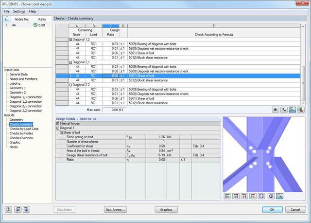
At first, the governing joint designs are arranged in groups and displayed with the basic geometry of the joint in the first result window. In the other result tables, you can see all fundamental design details such as the load-carrying capacity of anchors, stresses in welds, and others.
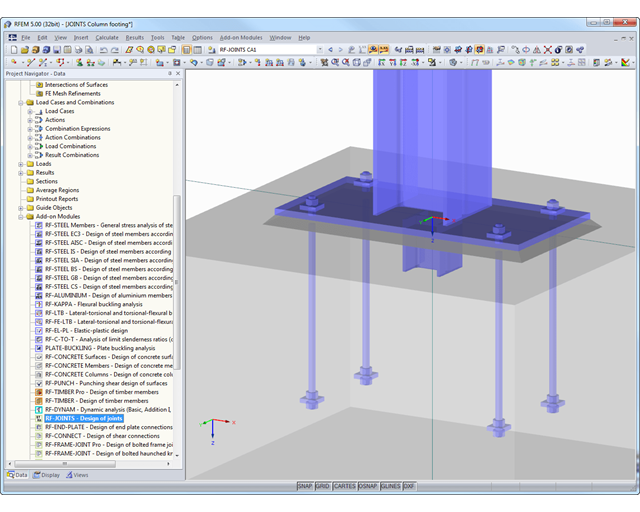
Dimensions, material specifications, and welds that are important for the construction of the connection are visible immediately and can be printed out. It is possible to visualize the connections in RF-/JOINTS Steel - Column Base or in the RFEM/RSTAB model.
All graphics can be included in the RFEM/RSTAB printout report or printed directly. Due to the scaled output, an optimal visual check is possible as early as in the design phase.
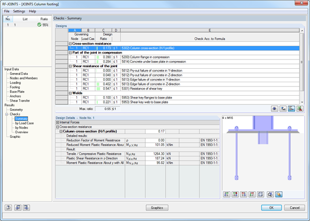
After the calculation, RF-/JOINTS Steel - Column Base displays the following design results:
- Base plate bending
- Anchor tension and anchor shear force
- Shear key strength
- Concrete compression / failure of concrete edges
- Friction
- Welds
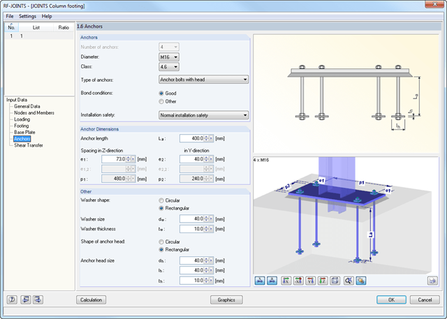
After you have selected the anchorage type and the design standard in the first input window, define the node in Window 1.2 that is to be imported from RFEM/RSTAB and where the footing anchorage is to be designed.
Optionally, you can define the column cross-section and material manually. In the next input windows, you can define the parameters of the base point, such as The loading is imported from RFEM/RSTAB or, in the case of a manual joint definition, the loads are entered.
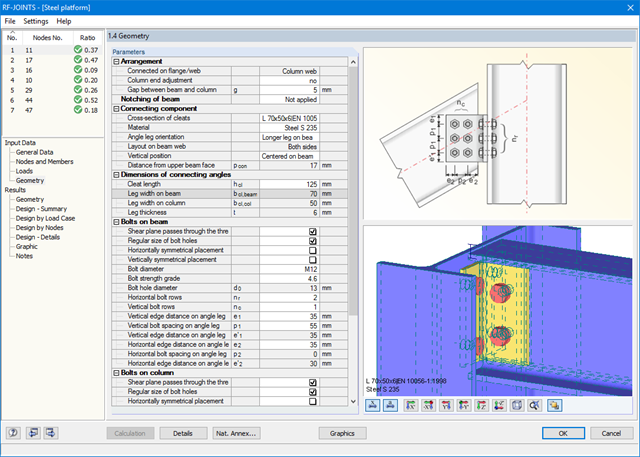
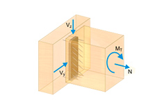
All joint types are considered with the moment release at the column flange, or at the column web in the case of a rotated column. Therefore, the module determines the eccentric moment of a web cleat and fin plate connection, which additionally affects the bolt group at the girder flange.
Further eccentric moments may result from the locations of the angles and sheets. In the case of cleat connection, the forces are transferred separately. Shear forces act on the cleat; tension forces and stabilizing moment are assigned to the bolts. Before the calculation, the connection is checked for geometrical plausibility; for example, the bolt hole spacing and edge distance of the bolts.
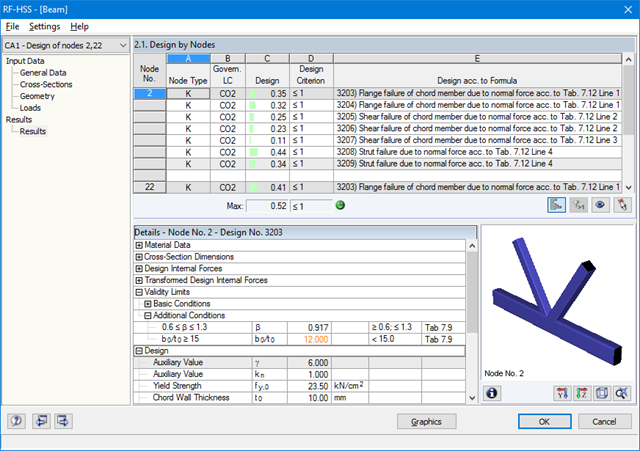
The design includes detailed information about analyzed internal forces, validity limits, and design conditions. Design failures are clearly marked in the result overview.
All input and result data are also documented in the general RFEM/RSTAB printout report. Separate design cases allow flexible analysis of the individual components in large structures.