19 Results
View Results:
Sort by:
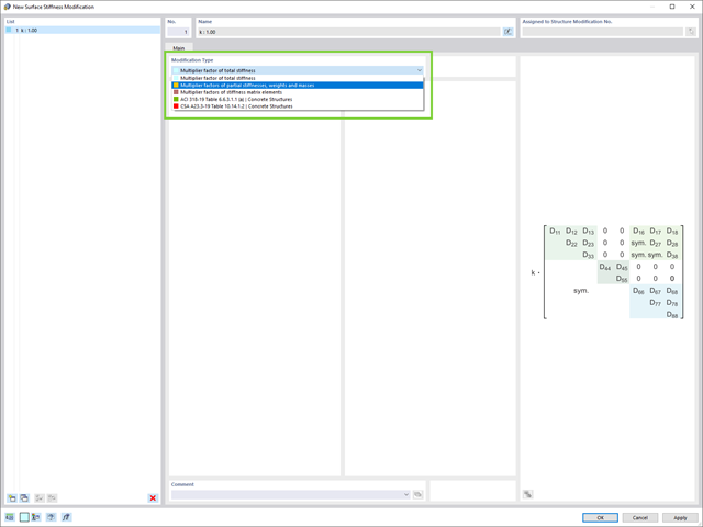
Do you want to modify surface stiffnesses? There are now two new types available for you:
- Multiplication factor of total stiffness
- Multiplication factors of partial stiffnesses, weights, and masses

- 002110
- General
- Optimization & Cost / CO2 Emission Estimation for RFEM 6
- Optimization & Cost / CO2 Emission Estimation for RSTAB 9
There are two methods that you can use for the optimization process, with which you can find optimal parameter values according to a weight or deformation criterion.
The most efficient method with the littlest calculation time is the near-natural particle swarm optimization (PSO). Have you heard or read about it? This artificial intelligence (AI) technology has a strong analogy to the behavior of flocks of animals, looking for a resting place. In such swarms, you can find many individuals (cf. optimization solution - for example, weight) who like to stay in a group and follow the group movement. Let's assume that each individual swarm member has a need to rest at an optimal resting place (cf. best solution - for example, lowest weight). This need increases as the resting place is approached. Thus, the swarm behavior is also influenced by the properties of the space (cf. result diagram).
Why the excursion into biology? Quite simply – the PSO process in RFEM or RSTAB proceeds in a similar way. The calculation run starts with an optimization result from a random assignment of the parameters to be optimized. It repeatedly determines new optimization results with varied parameter values, which are based on the experience of the previously performed model mutations. The process continues until the specified number of possible model mutations is reached.
As an alternative to this method, the program also offers you a batch processing method. This method attempts to check all possible model mutations by randomly specifying the values for the optimization parameters until a predetermined number of possible model mutations is reached.
After calculating a model mutation, both variants also check the respective activated design results of the add-ons. Furthermore, they save the variant with the corresponding optimization result and value assignment of the optimization parameters if the utilization is < 1.
You can determine the estimated total costs and emission from the respective sums of the individual materials. The sums of the materials are composed of the weight-based, volume-based, and area-based partial sums of the member, surface, and solid elements.
The program supports you: It determines the bolt forces on the basis of the FE analysis model and evaluates them automatically. The add-on performs the standard-compliant design of bolt resistance for failure cases, such as tension, shear, hole bearing, and punching, and clearly displays all required coefficients.
Do you want to perform weld design? The welds are modeled as elastic-plastic surface elements, and their stresses are read out from the FE analysis model. The plasticity criteria is set in the way that they represent failure according to AISC J2-4, J2-5 (strength of welds), and J2-2 (strength of base metal). The design can be performed with the partial safety factors of the selected National Annex of EN 1993‑1‑8.
The plates in the connection are designed plastically by comparing the existing plastic strain to the allowable plastic strain. The default setting is 5% according to EN 1993‑1‑5, Annex C, but can be adjusted by user-defined specifications, as well as 5% for AISC 360.
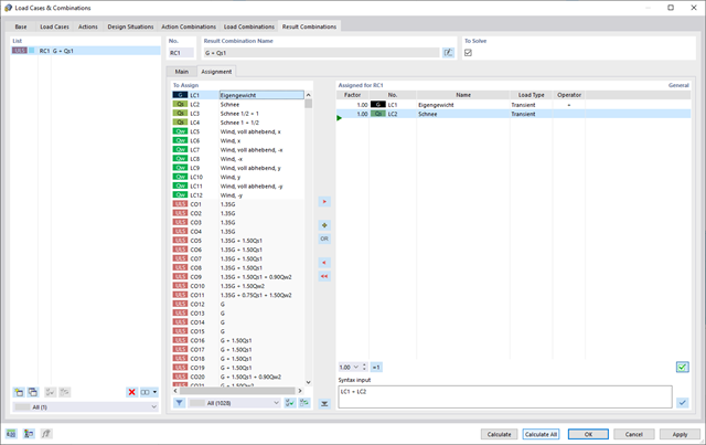
RFEM 6 offers you a wide range of helpful and efficient functions for working with load combinations. You can add the load cases included in load combinations together and then calculate them in consideration of the corresponding factors (partial safety and combination factors, coefficients regarding consequence classes, and so on). Generate the load combinations automatically in compliance with the combination expressions of the standard. You can perform the calculation according to the linear static analysis, second-order analysis, or large deformation analysis, as well as for post-critical analysis. Optionally, you can define whether the internal forces should be related to the deformed or non-deformed structure.
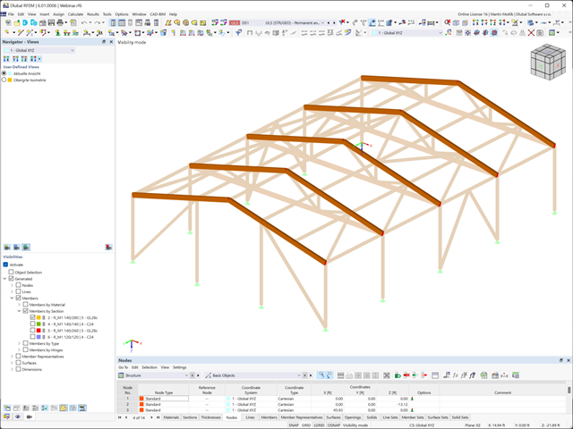
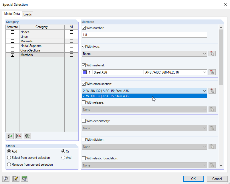
A clear display is a prerequisite for your efficient and fast work with the program. Select user-defined views from different angles to facilitate the result evaluation. Using "visibilities", you can also divide the model into user-defined and generated partial views that fulfill certain criteria. It is thus possible, for example, to activate only the surfaces of a specific material or members with a particular cross-section for the display.
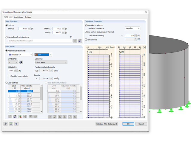
Rely on the Dlubal programs even in windy matters. RFEM and RSTAB provide a special interface for exporting models (that is, structures defined by members and surfaces) to RWIND 2. There, the wind directions to be analyzed for your project are defined by means of related angular positions about the vertical model axis. Furthermore, the elevation-dependent wind profile and turbulence intensity profile are defined on the basis of a wind standard. These specifications result in specific load cases, depending on the angle. For this, the fluid parameters, turbulence model properties, and iteration parameters that are all stored globally are helpful. You can extend these load cases by partial editing in the RWIND 2 environment using terrain or environment models from STL vector graphics.
As an alternative, you can also run RWIND 2 manually and without the interface application in RFEM or RSTAB. In this case, the structures and terrain environment in the program are directly modeled by imported STL and VTP files. You can define the height-dependent wind load and other fluid-mechanical data directly in RWIND 2.
Due to its versatile applicability, RWIND 2 is always at your side to support you in your individual projects.

- Nonlinear member types, such as tension and compression members or cables
- Member nonlinearities, such as failure, tearing, yielding under tension or compression
- Support nonlinearities, such as failure, friction, diagram, and partial activity
- Release nonlinearities, such as friction, partial activity, diagram, and fixed if positive or negative internal forces
- Design of the following roof types:
- Monopitch roof
- Duopitch Roof
- Curved roof
- All roof shapes allow for a free selection of stiffening diagonals. The following types are available:
- Falling diagonals
- Rising diagonals
- Crossing diagonals with verticals
- Crossing diagonals without verticals
- Crossing diagonals with steel strips (ties)
- Consideration of window rows in the ridge by selecting an inner intermediate part.
- For design according to EC 5 (EN 1995), the following National Annexes are available:
-
 DIN EN 1995-1-1/NA:2013-08 (Germany)
 -
 NBN EN 1995-1-1/ANB:2012-07 (Belgium)
 -
 DK EN 1995-1-1/NA:2011-12 (Denmark)
 -
 SFS EN 1995-1-1/NA:2007-11 (Finland)
 -
 NF EN 1995-1-1/NA:2010-05 (France)
 -
 UNI EN 1995-1-1/NA:2010-09 (Italy)
 -
 NEN EN 1995-1-1/NB:2007-11 (Netherlands)
 -
 ÖNORM B 1995-1-1:2015-06 (Austria)
 -
 PN EN 1995-1-1/NA:2010-09 (Poland)
 -
 SS EN 1995-1-1 (Sweden)
 -
 STN EN 1995-1-1/NA:2008-12 (Slovakia)
 -
 SIST EN 1995-1-1/A101:2006-03 (Slovenia)
 -
 CSN EN 1995-1-1:2007-09 (Czech Republic)
 -
 BS EN 1995-1-1/NA:2009-10 (the United Kingdom)
-
- Simple geometry input with illustrative graphics
- Automatic generation of wind loads
- Automatic creation of required combinations for the ultimate and serviceability limit states, as well as fire resistance design
- Free definition of the load cases to be used
- Extensive material library
- Optional extension of material library by further materials
- Extensive library of permanent loads
- Allocation of framework to service classes and specification of service class categories
- Determination of design ratios, support forces, and deformations
- Info icon indicating successful or failed design
- Color reference scales in result tables
- Direct data export to MS Excel
- DXF interface for preparation production documents in CAD
- Program languages: English, German, Czech, Italian, Spanish, French, Portuguese, Polish, Chinese, Dutch, and Russian
- Verifiable printout report, including all required designs. Printout report available in many output languages; for example, English, German, French, Italian, Spanish, Russian, Czech, Polish, Portuguese, Chinese, and Dutch.
- In the ultimate limit state design, the stiffness of the hinge is divided by the partial safety factor and in the serviceability limit state design calculated using the mean stiffnesses. The limit values for the ultimate and the serviceability limit states can be defined separately.

- Import of materials, cross-sections, and internal forces from RFEM/RSTAB
- Steel design of thin‑walled cross‑sections according to EN 1993‑1‑1:2005 and EN 1993‑1‑5:2006
- Automatic classification of cross-sections according to EN 1993-1-1:2005 + AC:2009, Cl. 5.5.2, and EN 1993-1-5:2006, Cl. 4.4 (cross-section class 4), with optional determination of effective widths according to Annex E for stresses under fy
- Integration of parameters for the following National Annexes:
-
DIN EN 1993-1-1/NA:2015-08 (Germany)
-
ÖNORM B 1993-1-1:2007-02 (Austria)
-
NBN EN 1993-1-1/ANB:2010-12 (Belgium)
-
 BDS EN 1993-1-1/NA:2008 (Bulgaria)
 -
DS/EN 1993-1-1 DK NA:2015 (Denmark)
-
SFS EN 1993-1-1/NA:2005 (Finland)
-
NF EN 1993-1-1/NA:2007-05 (France)
-
 ELOT EN 1993-1-1 (Greece)
 -
UNI EN 1993-1-1/NA:2008 (Italy)
-
 LST EN 1993-1-1/NA:2009-04 (Lithuania)
 -
 UNI EN 1993-1-1/NA:2011-02 (Italy)
 -
 MS EN 1993-1-1/NA:2010 (Malaysia)
 -
NEN EN 1993-1-1/NA:2011-12 (Netherlands)
- NS EN 1993-1-1/NA:2008-02 (Norway)
-
PN EN 1993-1-1/NA:2006-06 (Poland)
-
 NP EN 1993-1-1/NA:2010-03 (Portugal)
 -
 SR EN 1993-1-1/NB:2008-04 (Romania)
 -
SS EN 1993-1-1/NA:2011-04 (Sweden)
-
 SS EN 1993-1-1/NA:2010 (Singapore)
 -
STN EN 1993-1-1/NA:2007-12 (Slovakia)
-
SIST EN 1993-1-1/A101:2006-03 (Slovenia)
-
 UNE EN 1993-1-1/NA:2013-02 (Spain)
 -
CSN EN 1993-1-1/NA:2007-05 (Czech Republic)
-
BS EN 1993-1-1/NA:2008-12 (the United Kingdom)
-
 CYS EN 1993-1-1/NA:2009-03 (Cyprus)
 - In addition to the National Annexes (NA) listed above, you can also define a specific NA, applying user‑defined limit values and parameters.
- Automatic calculation of all required factors for the design value of flexural buckling resistance Nb,Rd
- Automatic determination of the ideal elastic critical moment Mcr for each member or set of members on every x-location according to the Eigenvalue Method or by comparing moment diagrams. You only have to define the lateral intermediate supports.
- Design of tapered members, unsymmetric sections or sets of members according to the General Method as described in EN 1993-1-1, Cl. 6.3.4
- In the case of the General Method according to Cl. 6.3.4, optional application of "European lateral-torsional buckling curve" according to Naumes, Strohmann, Ungermann, Sedlacek (Stahlbau 77 [2008], pp. 748‑761)
- Rotational restraints can be taken into account (trapezoidal sheeting and purlins)
- Optional consideration of shear panels (for example, trapezoidal sheeting and bracing)
- RF-/STEEL Warping Torsion module extension (license required) for stability analysis according to the second-order analysis as stress analysis including consideration of the 7th degree of freedom (warping)
- Module extension RF-/STEEL Plasticity (license required) for plastic analysis of cross‑sections according to Partial Internal Forces Method (PIFM) and Simplex Method for general cross‑sections (in connection with the RF‑/STEEL Warping Torsion module extension, it is possible to perform the plastic design according to the second‑order analysis)
- Module extension RF-/STEEL Cold-Formed Sections (license required) for ultimate and serviceability limit state designs for cold-formed steel members according to the EN 1993-1-3 and EN 1993-1-5 standards
- ULS design: Selection of fundamental or accidental design situations for each load case, load combination, or result combination
- SLS design: Selection of characteristic, frequent, or quasi-permanent design situations for each load case, load combination, or result combination
- Tension analysis with definable net cross-section areas for member start and end
- Weld designs of welded cross-sections
- Optional calculation of warp spring for nodal support on sets of members
- Graphic of design ratios on cross-section and in RFEM/RSTAB model
- Determination of governing internal forces
- Filter options for graphical results in RFEM/RSTAB
- Representation of design ratios and cross‑section classes in the rendered view
- Color scales in result windows
- Automatic cross-section optimization
- Transfer of optimized cross-sections to RFEM/RSTAB
- Parts lists and quantity surveying
- Direct data export to MS Excel
- Verifiable printout report
- Possibility to include the temperature curve in the report
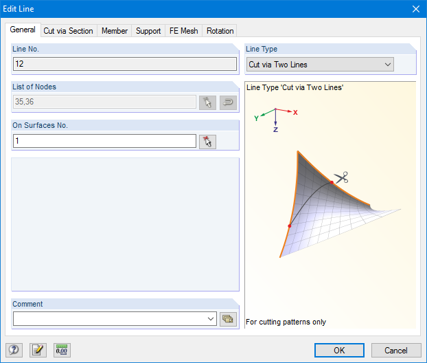
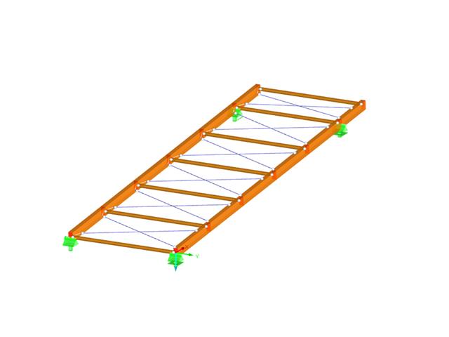
RF-CUTTING-PATTERN is activated by selecting the respective option in the Options tab in General Data of any RFEM model. After activating the add‑on module, a new object, "Cutting Patterns", is displayed under Model Data. If the membrane surface distribution for cutting in the basic position is too large, you can divide the surface by cutting lines (line types "Cut via Two Lines" or "Cut via Section") in the corresponding partial strips.
Then you can define the individual entries for each cutting pattern using the "Cutting Pattern" object. Here you can set boundary lines, compensations, and allowances.
Steps of the working sequence:
- Creation of cutting lines
- Creation of the pattern by selecting its boundary lines or using a semi‑automatic generator
- Free selection of warp and weft orientation by entering an angle
- Application of compensation values
- Optional definition of different compensations for boundary lines
- Different allowances (welding, boundary line)
- Preliminary representation of the cutting pattern in the graphic window at the side without starting the main nonlinear calculation
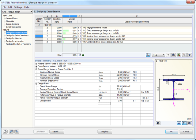
The fatigue strength design is based on the analysis using damage equivalent factors. The damage equivalent stress ranges ΔσE,2 and ΔτE,2 related to 2*106 stress cycles have to be compared to the limit values of the fatigue strength ΔσC or ΔτC for 2*106 stress cycles of the corresponding detail, taking into account the partial safety factors.
In this way, the individual design requirements are specified. Separate design cases enable flexible analysis of selected members, sets of members, and actions, as well as of individual cross‑sections. Design-relevant parameters such as B. selecting the design concept as well as partial safety factors can be defined freely.
- Import of results from RSTAB
- Integrated material and cross-section library
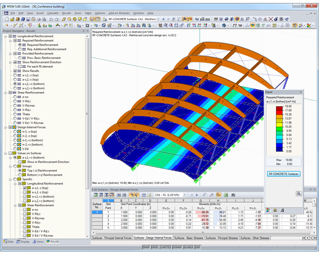
- The module extension EC2 for RSTAB enables design of reinforced concrete according to EN 1992-1-1 (Eurocode 2) and the following National Annexes:
-
DIN EN 1992-1-1/NA/A1:2015-12 (Germany)
-
ÖNORM B 1992-1-1:2018-01 (Austria)
-
Belgium NBN EN 1992-1-1 ANB:2010 for design at normal temperature, and NBN EN 1992-1-2 ANB:2010 for fire resistance design (Belgium)
-
BDS EN 1992-1-1:2005/NA:2011 (Bulgaria)
-
EN 1992-1-1 DK NA:2013 (Denmark)
-
NF EN 1992-1-1/NA:2016-03 (France)
-
SFS EN 1992-1-1/NA:2007-10 (Finland)
-
UNI EN 1992-1-1/NA:2007-07 (Italy)
-
 LVS EN 1992-1-1:2005/NA:2014 (Latvia)
 -
LST EN 1992-1-1:2005/NA:2011 (Lithuania)
-
MS EN 1992-1-1:2010 (Malaysia)
-
NEN-EN 1992-1-1+C2:2011/NB:2016 (Netherlands)
- NS EN 1992-1 -1:2004-NA:2008 (Norway)
-
PN EN 1992-1-1/NA:2010 (Poland)
-
NP EN 1992-1-1/NA:2010-02 (Portugal)
-
SR EN 1992-1-1:2004/NA:2008 (Romania)
-
SS EN 1992-1-1/NA:2008 (Sweden)
-
SS EN 1992-1-1/NA:2008-06 (Singapore)
-
STN EN 1992-1-1/NA:2008-06 (Slovakia)
-
SIST EN 1992-1-1:2005/A101:2006 (Slovenia)
-
UNE EN 1992-1-1/NA:2013 (Spain)
-
CSN EN 1992-1-1/NA:2016-05 (Czech Republic)
-
BS EN 1992-1-1:2004/NA:2005 (United Kingdom)
-
 CPM 1992-1-1:2009 (Belarus)
 -
CYS EN 1992-1-1:2004/NA:2009 (Cyprus)
-
- In addition to the National Annexes (NA) listed above, you can also define a specific NA, applying user‑defined limit values and parameters.
- Optional presetting of partial safety factors, reduction factors, neutral axis depth limitation, material properties, and concrete cover
- Determination of longitudinal, shear, and torsional reinforcement
- Design of tapered members
- Cross‑section optimization
- Representation of minimum and compression reinforcement
- Determination of editable reinforcement proposal
- Crack width analysis with optional increase of the required reinforcement in order to keep the defined limit values of the crack width analysis
- Nonlinear calculation with consideration of cracked cross‑sections (for EN 1992‑1‑1:2004 and DIN 1045‑1:2008)
- Considering tension stiffening
- Considering creep and shrinkage
- Deformations in cracked sections (state II)
- Graphical representation of all result diagrams
- Fire resistance design according to the simplified method (zone method) according to EN 1992‑1‑2 for rectangular and circular cross‑sections. Thus, fire resistance design of brackets is possible as well.
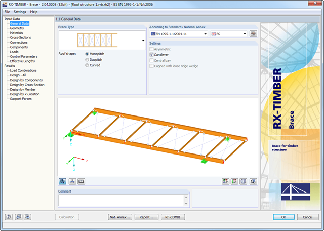
The geometry is entered by means of templates, as in all other programs of the RX‑TIMBER family. By selecting the roof structure, you define the base geometry, which can be adjusted by user-defined settings. The relevant timber grade of the material can be selected from the material library. All material grades for glulam, hardwood, poplar and softwood timber specified in EN 1995-1-1 are available. Furthermore, it is possible to generate a strength class with user-defined material properties in order to extend the library.
Since the stiffening bracing includes the steel cross-sections, current steel grades are integrated in the library as well. Therefore, rolled and welded cross-sections are also available. Stiffening of coupling elements can be considered in Table 1.5 Connections as translational and rotational spring stiffnesses. The program handles these stiffnesses with a stiffness divided by the partial safety factor for the design of the bearing capacity and with the mean values of the stiffness for the serviceability limit state design. The loading can be entered directly as a lateral load (equivalent lateral load) resulting from a truss girder design.
The wind load is applied automatically to all four sides of the structure. Additionally, you can specify user-defined loads; for example, concentrated loads from columns (buckling load). According to the generated loads, the program automatically creates combinations for the ultimate and serviceability limit states as well as for fire resistance design in the background. The generated combinations can be considered or adjusted by user-defined specifications.
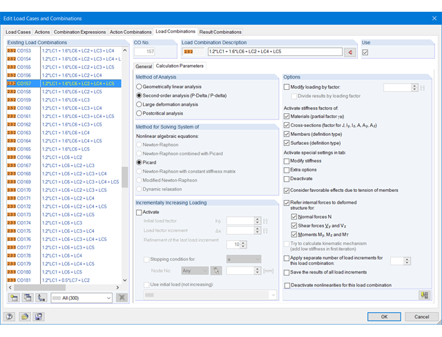
The load cases included in load combinations are added together and then calculated in consideration of the corresponding factors (partial safety and combination factors, coefficients regarding consequence classes, and so on). The load combinations can be created automatically in compliance with the combination expressions of the standard. The calculation can be performed according to the geometrically linear, second-order, or large deformation or as per the post-critical analysis. Optionally, you can define whether the internal forces should be related to the deformed or non-deformed structure.
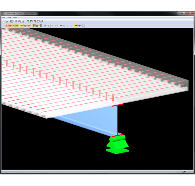
Various buttons allow you to directly change the perspective and work plane. By zooming, rotating, and shifting the structure you can quickly adjust the appropriate view. Partial views represent specific structural parts clearly. Inactive objects can be displayed transparently in the background. By selecting structural elements according to special criteria, it is possible to group objects in a simple way.
Results are displayed in result tables sorted by required designs. Clear arrangement of the results allows for easy orientation and evaluation.
Ultimate Limit State Design:
- Bending and shear force resistance with interaction
- Partial shear connecting of ductile and non-ductile connecting elements
- Determination of required shear connectors and their distribution
- Design of longitudinal shear force resistance
- Design of connection with shear connectors and of connector perimeter
- Results of governing support reactions for construction and composite stage, including loads of construction supports
- Lateral-torsional buckling analysis (for continuous beams and cantilevered girders)
- Check of cross-section classes as well as of plastic and elastic cross-section properties
Serviceability limit state design:
- Deflection Analysis
- Deformations and initial pre-cambering determined with ideal cross-section properties from creep and shrinkage
- Analysis of natural frequencies
- Crack width analysis
- Determination of support forces
All data are documented in a clearly arranged printout report, including graphics. In case of any modification, the printout report is updated automatically. COMPOSITE-BEAM is a stand-alone program and does not require the RSTAB license.
In accordance with DIN 18800, Part 2, the designs are carried out separately for flexural buckling and lateral-torsional buckling to simplify the calculation. Generally, the flexural buckling design is performed in the framework plane using the stress analysis of the planar structure according to the second-order analysis, considering design loads and pre-deformations.
The lateral-torsional buckling design is performed on an individual member detached from the entire structure by using defined boundary conditions and loads in accordance with the elastic-elastic method.
RF-/FE-LTB searches for the governing failure mode by means of the critical load factor which describes flexural, torsional, and lateral-torsional buckling, or the combination of all failure modes, depending on the model and load applied. Then, the module performs recalculation to obtain the required operands.
Detail settings control whether the critical load factor is calculated due to loss of stability (providing the material is defined by infinitely elastic properties), or with stress limitation.
If necessary, you can adjust the size of the finite elements. You can also modify the partial safety factor γM. In RF-/FE-LTB, iteration parameters are preset appropriately to calculate all common models, but can be adjusted individually.
- Integration in RFEM/RSTAB with automatic geometry recognition and transfer of internal forces
- Optional manual definition of connections
- Extensive library of hollow sections for chords and struts:
- Round sections
- Square sections
- Rectangular sections
- Implemented steel grades: S 235, S 275, S 355, S 420, S 450, and S 460
- Various types of connections available, depending on the standard specifications:
- K connection (gap/overlapping)
- KK connection (spatial)
- N connection (gap/overlapping)
- KT connection (gap/overlapping)
- DK connection (gap/overlapping)
- T connection (planar)
- TT connection (spatial)
- Y connection (planar)
- X connection (planar)
- XX connection (spatial)
- Selection of partial safety factors according to the National Annex for Germany, Austria, Czech Republic, Slovakia, Poland, Slovenia, Switzerland, or Denmark
- Adjustable angles between struts and chords
- Optional chord rotation of 90° for rectangular hollow sections
- Consideration of gaps between struts or overlapping struts
- Optional consideration of additional nodal forces
- Design of the connection as the maximum load-bearing capacity of the struts of a truss for axial forces and bending moments
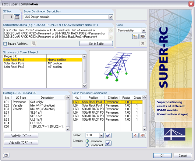
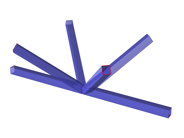
For superpositioning, it is necessary to select one of the integrated standards. The partial safety factors are preset by default. It is also possible to create a new standard and to save it with the user-defined safety factors.
The combination criterion defines which load cases, load combinations, or result combinations are to be considered by which model. The actions can be scaled by factors and classified as 'permanent' or 'potentially'. Alternative examinations in the form of a 'or' superposition are also possible. Graphic representations facilitate the allocation of the relevant models.
When determining extreme values, SUPER-RC imports the results of structures and superimposes them according to the combination criterion. The results are compared using the member and node numbers.