
Using the "Rib" component, you can define any number of longitudinal ribs on a member plate. By defining a reference object, you can automatically specify welds on it.
The "Rib" component can also be arranged on circular hollow sections. Dafür wird zusätzlich die Vorgabe der Winkel zwischen den Rippen benötigt.

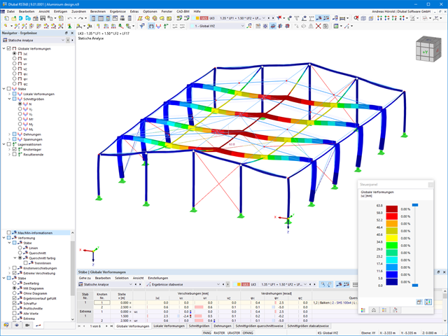
As soon as the program has completed the calculation, the summary of the results is listed. All result windows are integrated in the main program RFEM/RSTAB. You will find all the results arranged in tables; they can be displayed for each individual time step or as an envelope, and you also have the option of displaying the results graphically as well as animating them.
The results from the time history analysis can be displayed in the calculation diagrams. All the results are shown as a function of time. You can export the numeric values to MS Excel.
All result tables and graphics are part of the RFEM/RSTAB printout report. In this way, you can ensure clearly arranged documentation. You can also export the tables to MS Excel.
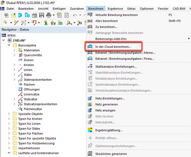
- Outsource calculation on a computing server in the cloud
- Option to select different powerful computing servers
- Clearly arranged display of all calculation tasks in the Extranet
- Calculated files are available for download for two months
- Virtually unlimited computing capacity using cloud technology

With the Concrete Design add-on, you can perform the fatigue design of members and surfaces according to EN 1992‑1‑1, Chapter 6.8.
For the fatigue design, you can optionally select two methods or design levels in the design configurations:
- Design Level 1: Simplified design according to 6.8.6 and 6.8.7(2): The simplified design is performed for frequent action combinations according to EN 1992‑1‑1, Chapter 6.8.6 (2), and EN 1990, Eq. (6.15b) with the traffic loads relevant in the serviceability state. A maximum stress range according to 6.8.6 is designed for the reinforcing steel. The concrete compressive stress is determined by means of the upper and lower allowable stress according to 6.8.7(2).
- Design Level 2: Design of damage equivalent stress acc. to 6.8.5 and 6.8.7(1) (simplified fatigue design): The design using damage equivalent stress ranges is performed for the fatigue combination according to EN 1992‑1‑1, Chapter 6.8.3, Eq. (6.69) with the specifically defined cyclic action Qfat.

In the "Shear Reinforcement" tab, you can select the option "Cross-ties over free rebars with active selection in graphic". It allows you to arrange additional cross-ties on free rebars of the longitudinal reinforcement.
You can activate or deactivate the position of the cross-ties in the Info Graphic. The cross-ties are applied for the ultimate limit state design and the structural design checks. They are available for the design according to EN 1992‑1‑1.
Go to Explanatory Video
When designing connections, you can now also insert a new member as a component directly in the Steel Joints add-on. This will only be considered for the connection design. You can use the Weld and Fasteners components to connect to other members.
Furthermore, it is possible to use the Member Section and Member Editor components and arrange reinforcement elements on the inserted member, such as stiffeners and tapers.
Go to Explanatory Video
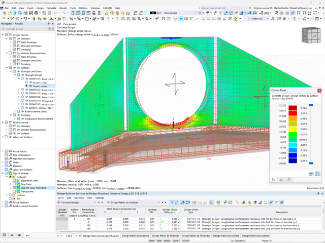
Do you prefer it clear? So do we! That's why all performed design checks for the design standard are displayed for you in a clear way. You determine a design criterion for each design check. You get design details, which include the initial values, intermediate results, and final results, arranged in a structured way for each design check. You can find the calculation process with the applied formulas, standard sources, and results in great detail in an information window in the design details.
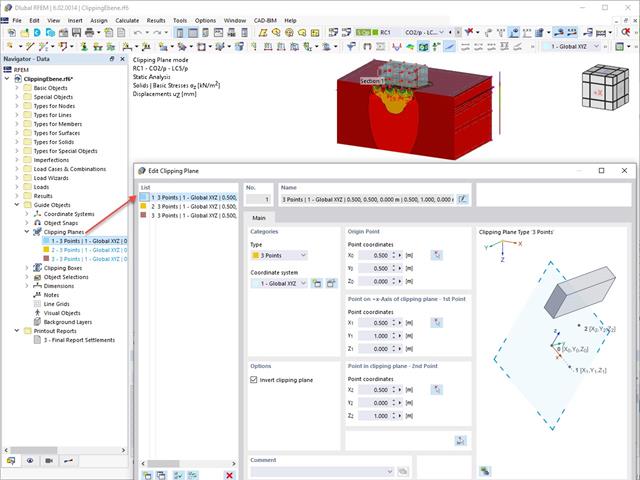
This feature also contributes to the clearly-arranged display of your results. Clipping planes are intersecting planes that you can place freely throughout the model. The zone in front of or behind the plane is consequently hidden in the display. This way, you can clearly and simply show the results in an intersection or a solid, for example.
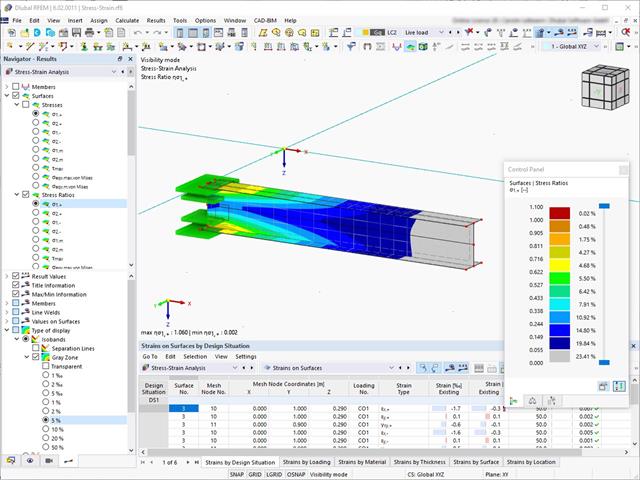
For stress-strain analyses, it is possible to define gray zones for nonrelevant value ranges in the result panel.

- A wide range of cross-sections, such as rectangular sections, square sections, T‑sections, circular sections, built-up cross-sections, irregular parametric cross-sections, and many others (suitability for design depends on the selected standard)
- Design of cross-laminated timber (CLT)
- Design of timber-based materials and laminated veneer lumber according to EC 5
- Design of tapered and curved members (design method according to the standard)
- Adjustment of the essential design factors and standard parameters is possible
- Flexibility due to detailed setting options for basis and extent of calculations
- Fast and clear results output for an immediate overview of the result distribution after the design
- Detailed output of the design results and essential formulas (comprehensible and verifiable result path)
- Numerical results clearly arranged in tables and graphical display of the results in the model
- Integration of the output into the RFEM/RSTAB printout report

RFEM/RSTAB also provides a range of functions for the case of a fire. The program allows for the automatic generation of load and result combinations for the accidental design situation of fire design. The members to be designed with the corresponding internal forces are imported directly from RFEM/RSTAB. Also, all information about the material and cross-section is stored. You don't need to do anything else.
You only define the parameters relevant for the fire resistance design by assigning a fire resistance configuration to the members and surfaces to be designed. Moreover, you can also make further detailed settings, such as the definition of the fire exposure on one side up to all sides.

- Manual specification of critical component temperature or automatic determination of component temperature for desired duration
- A wide range of fire curves: standard temperature-time curve, external fire curve, hydrocarbon curve
- Manual adjustment of the essential coefficients for the determination of the steel temperature
- Consideration of hot-dip galvanizing of structural components for the determination of the steel temperature
- Results of a temperature-time diagram for the gas and steel temperature
- Fire protection cladding as a contour or a box cladding with temperature-independent materials can be considered when determining the temperature
- Design of members made of carbon steel or stainless steel
- Cross-section design checks and stability analyses (equivalent member method) according to EN 1993‑1‑2, Clause 4.2.3
- Design checks of the cross-sections of Class 4 according to EN 1993‑1‑2, Annex E.

The structural analysis programs RFEM/RSTAB offer you a wide range of automated functions that make your dayily work easier. One of them is the automatic generation of load and result combinations for the accidental design situation of fire design. The members to be designed with the corresponding internal forces are imported directly from RFEM/RSTAB. You don't need to do anything else. The program has also already stored all information about the material and cross-section for you.
By assigning a fire resistance configuration to the members to be designed, you define the parameters relevant for the fire resistance design. Here you can manually specify the critical steel temperature at the design time. Or let the program to determine the temperature determined automatically for a specified fire duration. You can select from various fire temperature curves and fire protection measures. It is also possible to make further detailed settings, such as the definition of the fire exposure on all sides or three sides

Is a clear arrangement important for you? The program provides you with a clear overview of all performed design checks for the design standard. For each design check, it is necessary to determine a design criterion. There are also design details arranged in a structured way, including the initial values, intermediate results, and final results. You can laso find here an information window where the calculation process with the applied formulas, standard sources, and results is displayed in great detail.

- Many predefined components: Allow easy input of typical connection situations, such as end plates, angles, multi-wall sheets, cleats, fin plates
- Universally applicable basic components (plates, welds, bolts, auxiliary planes) for entering complex connection situations
- Graphical display of the connection geometry that is updated in parallel with the input
- The Steel Joints Template included in the add-on allows you to select from several connection types and, and once selected, it will be applied to your model.
- Wide range of cross-section shapes: Includes I-sections, channel sections, angles, T-sections, built-up cross-sections, RHS (rectangular hollow sections), and thin-walled sections
- The Template covers connections from three general categories: Rigid, Pinned, Truss
- Automatic adaptation of the connection geometry, even if the structural components are subsequently edited, based on the relative relation of the components

The structural analysis program provides you with a clear overview of all performed design checks for the design standard. You have to determine a design criterion for each design check. In addition to the ultimate limit state and the serviceability limit state design, the program checks the design rules of the standard. For each design check, there are the design details including the initial values, intermediate results, and final results, arranged in a structured way. An information window in the design details shows you the calculation process with the applied formulas, standard sources, and results in great detail.
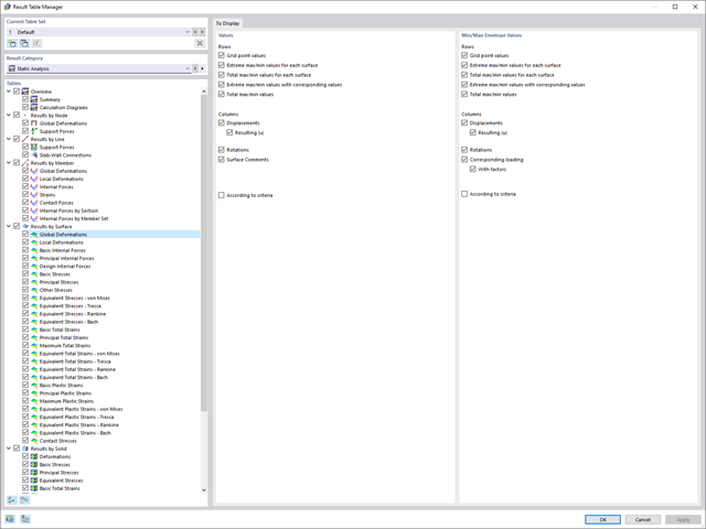
There are also optimizations for the clear arrangement of your results. To better display the results, you can reduce the displayed columns and rows with the new Result Table Manager.
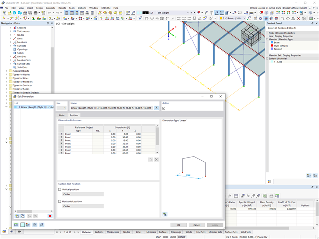
A clear arrangement of the Dlubal programs has a high priority. Therefore, the reference descriptions of incremental dimension lines are now given in tabular form for a better overview.
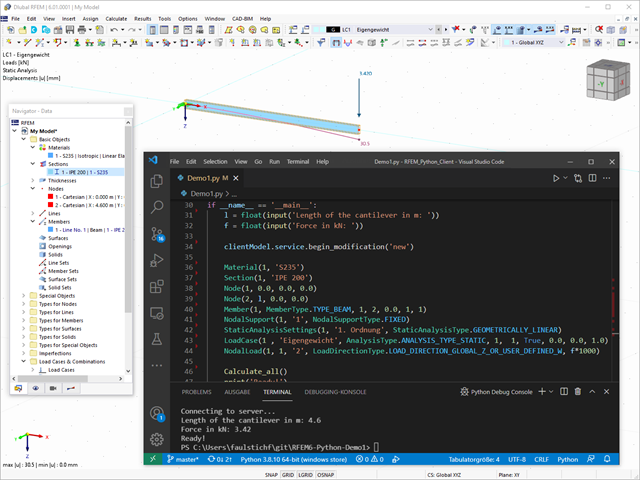
Webservice and API opens up a wide range of new possibilities for you. You can create your own desktop or web-based applications by controlling all objects included in RFEM 6 and RSTAB 9. By providing libraries and functions, you can develop your own design checks, effective modeling of parametric structures, as well as optimization and automation processes using the programming languages Python and C#. Does that sound exciting to you? Then find out more here!
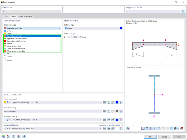
There are seven new cross-section distribution types available for members (including arrangement function for aligning to a straight edge):
- Tapered at both sides
- Tapered at start of member
- Tapered at end of member
- Duopitch
- Offset at both sides
- Offset at start of member
- Offset at end of member

By solving the numerical flow problem, you can obtain the following results on and around the model:
- Pressure on structure surface
- Coefficient Cp distribution on the structure surfaces
- Pressure field about the structure geometry
- Velocity field about the structure geometry
- Turbulence k-ω field about the structure geometry
- Turbulence k-ε field about the structure geometry
- Velocity vectors about the structure geometry
- Streamlines about the structure geometry
- Forces on member-shaped structures that were originally generated from member elements
- Convergence diagram
- Direction and size of the flow resistance of the defined structures
Despite this amount of information, RWIND 2 remains clearly arranged, as is typical for the Dlubal programs. You can specify freely definable zones for a graphic evaluation. Voluminously displayed flow results about the structure geometry are often confusing – you know the problem for sure. That's why RWIND Basic provides freely movable section planes for the separate display of the "solid results" in a plane. For the 3D branched streamline result, you have an option to select between a static and an animated display in the form of moving line segments or particles. This option helps you to represent the wind flow as a dynamic effect.
You can export all results as a picture or, especially for the animated results, as a video.
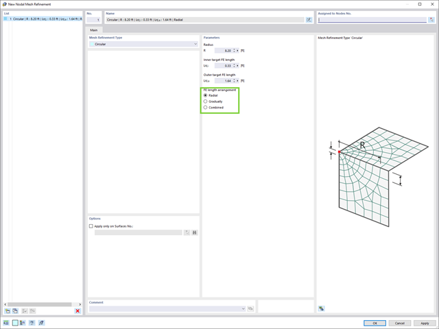
There's something new for you! To define odal mesh refinements, the options for FE length arrangement have been added:
- Radial
- Gradually
- Combined
Also, on the rendered model, you see your results in a clear color display. This allows you to precisely recognize the deformation or internal forces of a member, for example. If you want to set the colors and value ranges, you can do so in the control panel.

Compared to the RF‑/STEEL add-on module (RFEM 5 / RSTAB 8), the following new features have been added to the Stress-Strain Analysis add-on for RFEM 6 / RSTAB 9:
- Treatment of members, surfaces, solids, welds (line welded joints between two and three surfaces with subsequent stress design)
- Output of stresses, stress ratios, stress ranges, and strains
- Limit stress depending on the assigned material or a user-defined input
- Individual specification of the results to be calculated through freely assignable setting types
- Non-modal result details with prepared formula display and additional result display on the cross-section level of members
- Output of the design check formulas used

- 002108
- General
- Optimization & Cost / CO2 Emission Estimation for RFEM 6
- Optimization & Cost / CO2 Emission Estimation for RSTAB 9
- Artificial intelligence technology (AI): Particle swarm optimization (PSO)
- Structure optimization according to the minimum weight or deformation
- Use of any number of optimization parameters
- Specification of variable ranges
- Optimization of cross-sections and materials
- Parameter definition types
- Optimization | Ascending or Optimization | Descending
- Application of parametric models and blocks
- Code-based JavaScript parametrization of blocks
- Optimization taking into account the design results
- Tabular display of the best model mutations
- Real-time display of the model mutations in the optimization process
- Model cost estimation by specifying unit prices
- Determination of the global warming potential GWP when realizing the model by estimating the CO2 equivalent
- Specification of weight-, volume-, and area-based units (price and CO2e)

- 002109
- General
- Optimization & Cost / CO2 Emission Estimation for RFEM 6
- Optimization & Cost / CO2 Emission Estimation for RSTAB 9
Did you know? The structural optimization in the programs RFEM and RSTAB is a completion of the parametric input. It is a parallel process beside the actual model calculation with all its regular calculation and design definitions. The add-on assumes that your model or block is built with a parametric context and is controlled in its entirety by global control parameters of the "optimization" type. Therefore, these control parameters have a lower and upper limit and a step size to delimit the optimization range. If you want to find optimal values for the control parameters, you have to specify an optimization criterion (for example, minimum weight) with the selection of an optimization method (for example, particle swarm optimization).
You can already find the cost and CO2 emission estimation in the material definitions. You can activate both options individually in each material definition. The estimation is based on a unit for unit cost or unit emission for members, surfaces, and solids. In this case, you can select whether to specify the units by weight, volume, or area.
- Stress determination using an elastic-plastic material model
- Design of masonry disc structures for compression and shear on the building model or single model
- Automatic determination of stiffness of a wall-slab hinge
- An extensive material database for almost all stone-mortar combinations available on the Austrian market (the product range is continuously being expanded, for other countries as well)
- Automatic determination of material values according to Eurocode 6 (ÖN EN 1996‑X)
- Option to create pushover analysis

As soon as the program has completed the calculation, the eigenvalues, natural frequencies and periods are listed. These result windows are integrated in the main program RFEM/RSTAB. You can find all mode shapes of the structure in tables and also have an option to display them graphically and to animate them.
All result tables and graphics are part of the RFEM/RSTAB printout report. In this way, you can ensure clearly arranged documentation. You can also export the tables to MS Excel.

Have you carried out the design successfully? The results of the deformation analysis are now listed in clearly arranged output tables or detailed dialog boxes with info text. The program shows you all intermediate values in a comprehensible manner. Graphical representation of design ratios and deformation in RFEM allows you for a quick overview of critical areas.
Due to the results output of the design checks with all intermediate results, you can follow the calculation to the smallest detail. The complete integration of results in the RFEM printout report ensures that you obtain verifiable structural design.
- Automatic import of internal forces from RFEM/RSTAB
- Ultimate limit state and serviceability limit state design checks
- User-defined limit values and parameters based on the integrated National Annexes (NA)
- Flexibility due to detailed setting options for basis and extent of calculations
- Fast and clear results output for an immediate overview of the result distribution after the design
- Graphical output of results integrated in RFEM/RSTAB; for example, design check ratios or required reinforcement
- Numerical results clearly arranged in tables and graphical display of the results in the model
- Integration of the output into the RFEM/RSTAB printout report