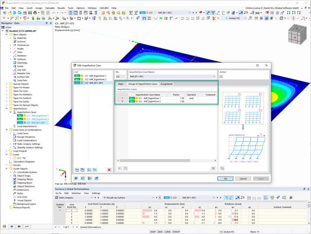
In the "Group of Imperfection Cases" imperfection case, you can enter several geometric imperfection cases. This allows you to carry out GMNIA analyses where several geometric imperfections have to be superimposed.
Go to Explanatory Video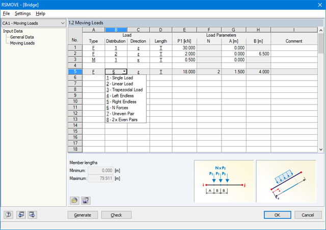
Sets of members with moving loads are selected graphically in the RFEM/RSTAB model. You can apply several different types of loads to one set of members at the same time.
By specifying the first load position, you can precisely display the load entering the runway of the continuous member. In the same way, it is possible to define whether a moving load consisting of various load applications is allowed to move beyond the end of continuous members (bridge) or not (crane runway).
The increment of the individual load positions is determined by the number of load cases generated for RFEM/RSTAB. You can also add loads to already existing RFEM/RSTAB load cases so that no additional superposition is required. Several load types are available, for example single, linear and trapezoidal loads as well as load pairs and several uniform concentrated loads.
It is possible to apply the loads in local and global directions. The application can refer to the true member length or to the projection in a global direction.
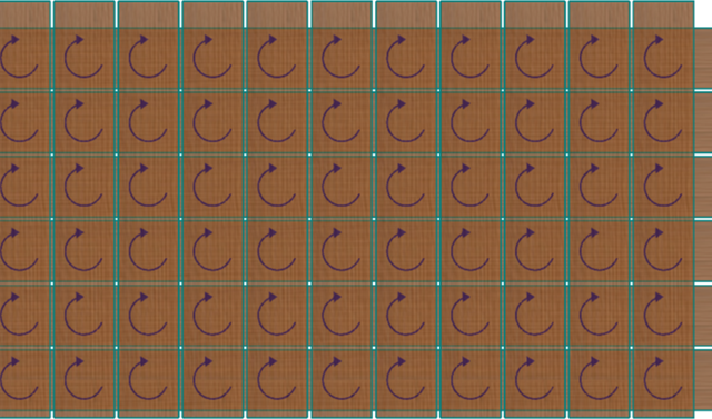
In the RF-LAMINATE add-on module for RFEM, the design of torsional shear stresses in the superposition of net and gross cross-section values is possible. The design is performed separately in the x- and y-directions. The loads on the intersection points of cross-laminated timber panels are checked.
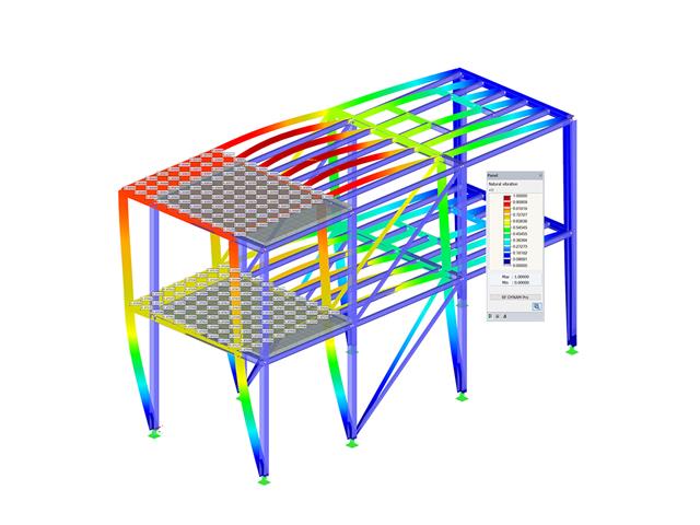
- Response spectra in accordance with different standards
- The following standards are implemented:
-
 EN 1998-1:2010 + A1:2013 (European Union)
 -
 DIN 4149:1981-04 (Germany)
 -
DIN 4149:2005-04 (Germany)
-
 IBC 2000 (USA)
 -
IBC 2009-ASCE/SEI 7-05 (USA)
-
IBC 2012/15 - ASCE/SEI 7-10 (USA)
-
IBC 2018 - ASCE/SEI 7-16 (USA)
-
 ÖNORM B 4015:2007-02 (Austria)
 -
 NTC 2018 (Italy)
 -
 NCSE-02 (Spain)
 -
 SIA 261/1:2003 (Switzerland)
 -
SIA 261/1:2014 (Switzerland)
-
SIA 261/1: 2020 (Switzerland)
-
 O.G. 23089 + OG 23390 (Turkey)
 -
 SANS 10160-4 2010 (South Africa)
 -
 SBC 301:2007 (Saudi Arabia)
 -
 GB 50011 - 2001 (China)
 -
GB 50011 - 2010 (China)
-
 NBC 2015 (Canada)
 -
 DTR BC 2-48 (Algeria)
 -
DTR RPA99 (Algeria)
-
 CFE Sismo 08 (Mexico)
 -
 CIRSOC 103 (Argentina)
 -
 NSR - 10 (Colombia)
 -
 IS 1893:2002 (India)
 -
 AS1170.4 (Australia)
 -
 NCh 433 1996 (Chile)
-
- The following National Annexes according to EN 1998‑1 are available:
-
DIN EN 1998-1/NA:2011-01 (Germany)
-
ÖNORM EN 1991-1-1:2011-09 (Austria)
-
 NBN - ENV 1998-1-1: 2002 NAD-E/N/F (Belgium)
 -
 ČSN EN 1998-1/NA:2007 (Czech Republic)
 -
 NF EN 1998-1-1/NA:2014-09 (France)
 -
UNI-EN 1991-1-1/NA:2007 (Italy)
-
 NP EN 1998-1/NA:2009 (Portugal)
 -
 SR EN 1998-1/NA:2004 (Romania)
 -
 STN EN 1998-1/NA:2008 (Slovakia)
 -
 SIST EN 1998-1:2005/A101:2006 (Slovenia)
 -
 CYS EN 1998-1/NA:2004 (Cyprus)
 -
 NA to BS EN 1998-1:2004:2008 (United Kingdom)
 - NS-EN 1998-1:2004 + A1:2013/NA:2014 (Norway)
-
- User-defined response spectra
- Direction-relative response spectrum approach
- Relevant mode shapes for the response spectrum can be selected manually or automatically (5% rule from EC 8 can be applied)
- Generated equivalent static loads are exported to load cases, separately for each modal contribution and separately for each direction
- Result combinations by modal superposition (SRSS and CQC rule) and direction superposition (SRSS or 100% / 30% rule)
- Signed results based on the dominant eigenmode can be displayed
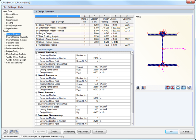
All results are arranged in result windows sorted by different topics. The design values are illustrated in the corresponding cross-section graphic. The design details cover all intermediate values.
General Stress Analysis
CRANEWAY performs the general stress analysis of a craneway girder by calculating the existing stresses and comparing them with the limit normal, limit shear, and limit equivalent stresses. Welds are also subjected to the general stress analysis with regard to parallel and vertical shear stresses and their superposition.
Fatigue Design
Fatigue design is performed for up to three cranes operating at the same time, based on the nominal stress concept according to EN 1993-1-9. In the case of fatigue design according to DIN 4132, a stress curve of crane passages is recorded for each stress point and evaluated according to the Rainflow method.
Buckling Analysis
Buckling analysis considers the local introduction of wheel loads according to the EN 1993-6 or DIN 18800-3 standards.
Deformation,
Deformation analysis is performed separately for the vertical and horizontal directions. The available related displacements are compared to the allowable values. You can specify the allowable deformation ratios individually in the calculation parameters.
Lateral-torsional buckling analysis
The lateral-torsional buckling analysis is performed in accordance with the second-order analysis for torsional buckling considering imperfections. The general stress analysis has to be fulfilled with the critical load factor greater than 1.00. As a result, CRANEWAY displays the corresponding critical load factor for all load combinations of the stress analysis.
Support forces
The program determines all support forces on the basis of the characteristic loads, including dynamic factors.
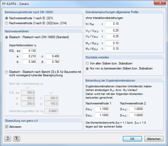
In a separate dialog box, you can specify extensive detailed settings for the design:
Design Method According to DIN 18800
- Design Method 1 According to El. (321)
- Design Method 2 According to El. (322)
Analysis method
- Elastic-Plastic according to DIN 18800
- Elastic-elastic according to a publication by Kretschmar, J./Österrieder, P./beirow, B.
Limit loading of general sections
- General sections – these include all cross-sections that cannot be assigned to single or double symmetric I-sections, box sections, or pipe sections – can also be designed according to the equivalent member method against flexural buckling. In this case, however, the plastic cross-section properties are determined without interaction conditions. The allowable application limits for this consideration depend on the ratio of the existing internal force to the fully plastic internal force. Five text boxes provide the option for user-defined control.
Check of limit (c/t)
- In this dialog section, you can activate or deactivate the check of c/t ratios.
Treatment of Result Combinations
- When designing a result combination, a result set is obtained due to the result superposition on each member location, which makes it impossible to clearly determine the moment factors. In this section, you can thus freely specify a global moment factor for a result combination design. The predefined values are on the safe side, regardless of the design method.
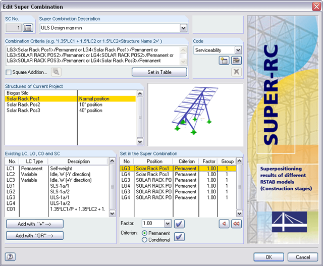
For superpositioning, it is necessary to select one of the integrated standards. The partial safety factors are preset by default. It is also possible to create a new standard and to save it with the user-defined safety factors.
The combination criterion defines which load cases, load combinations, or result combinations are to be considered by which model. The actions can be scaled by factors and classified as 'permanent' or 'potentially'. Alternative examinations in the form of a 'or' superposition are also possible. Graphic representations facilitate the allocation of the relevant models.
When determining extreme values, SUPER-RC imports the results of structures and superimposes them according to the combination criterion. The results are compared using the member and node numbers.
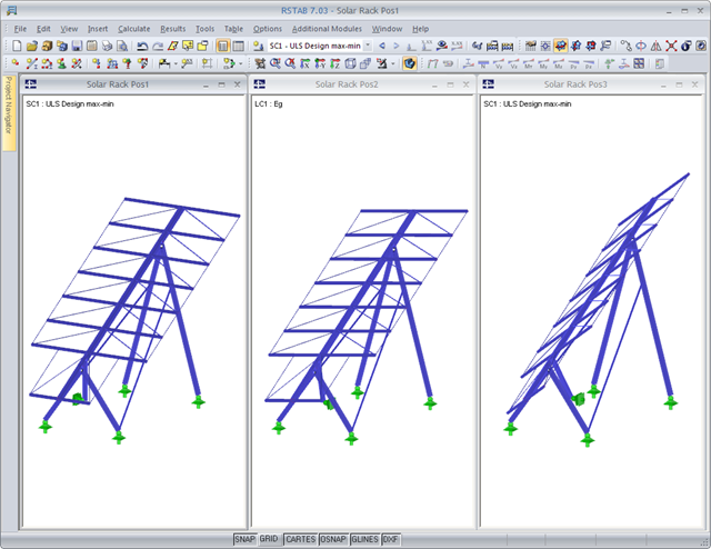
A basic model is created and saved under different names depending on the construction progress. These structural models are then used for the supercombination. The superpositioning can be performed in the same way as for an RSTAB result combination.
By modeling various construction or operational conditions, different geometric boundary conditions can be represented: It is possible to add or remove supports, members, or elastic foundation of the model, for example.
.png?mw=640&hash=9b9d807f48ef10cbb11e804ba19e570f258060db)
- Management of RSTAB models according to construction progress
- Definition of geometric boundary conditions for individual construction and operational conditions
- Access to load cases, load combinations, and result combinations of all structures
- Superposition of the different models in the form of an envelope of all extreme values
- Combination options according to the following standards:
-
Eurocode
-
DIN 18800:1990-11
-
DIN 1045:1988-07
-
DIN 1045-1:2008-08
-
DIN 1052:1988-04
-
to DIN 1055-100:2001-03
-
ÖNORM
- Serviceability (unscaled)
-
- Tabular and graphical result display
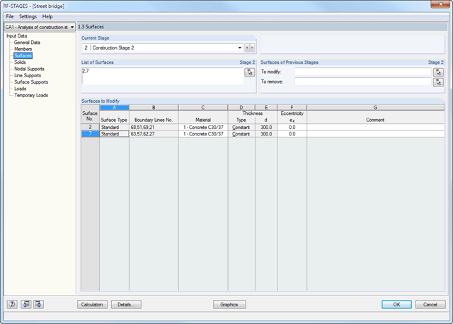
- Simple definition of construction stages in the RFEM/RSTAB structure including visualization
- Addition, removal, and modification of member, surface, and solid properties (such as member hinges, surface eccentricities, degrees of freedom for supports, and others)
- Optional superposition of construction stages with additional temporary loads; for example, mounting loads or mounting cranes, and others
- Consideration of nonlinear effects such as failure of a tension member, elastic foundations, or nonlinear supports
- Numerical and graphical result display for individual construction stages or as an envelope (Max/Min) of all construction stages
- Detailed printout report including all structural and load data of each construction stage