17 Wyniki
Wyświetl wyniki:
Sortuj według:
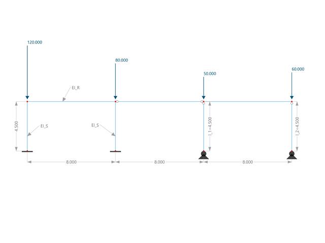
W tym przykładzie porównuje się długości efektywne i współczynnik obciążenia krytycznego, które mogą być obliczone w programie RFEM 6 przy użyciu rozszerzenia Stateczność konstrukcji, z obliczeniami ręcznymi. Układ konstrukcyjny stanowi sztywna rama z dwoma dodatkowymi słupami przegubowymi. Ten słup jest obciążany pionowymi obciążeniami skupionymi.
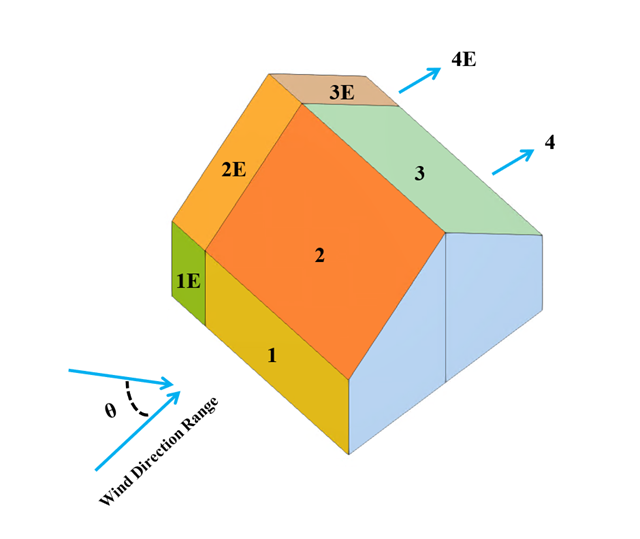
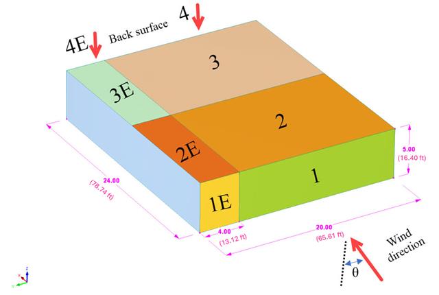
W bieżącym przykładzie walidacyjnym badany jest współczynnik ciśnienia wiatru (Cp) zarówno dla głównych elementów konstrukcyjnych (Cp,ave ), jak i drugorzędnych elementów konstrukcyjnych, takich jak systemy okładziny lub fasady (Cp,local ) w oparciu o NBC 2020 [1] and Baza danych japońskich tuneli aerodynamicznych dla niskiego budynku o nachyleniu 45 stopni. Zalecane ustawienie dla trójwymiarowego dachu płaskiego z ostrym okapem zostanie opisane w następnej części.
W poniższym przykładzie sprawdzamy wartość ciśnienia wiatru zarówno dla ogólnego projektowania konstrukcyjnego (Cp,10 ), jak i lokalnego projektowania konstrukcyjnego, takiego jak okładziny lub fasady (Cp,1 ) w oparciu o EN 1991-1-4, przykład dachu płaskiego [1] and Baza danych japońskich tuneli aerodynamicznych . Zalecane ustawienie dla trójwymiarowego dachu płaskiego z ostrym okapem zostanie opisane w następnej części.
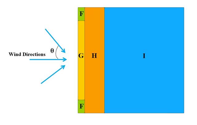
W bieżącym przykładzie walidacyjnym badamy współczynnik parcia wiatru (Cp) płaskiego dachu i ścian za pomocą ASCE7-22 [1]. W rozdziale 28.3 (Obciążenia wiatrem - główny układ odporności na siłę wiatru) i na Rysunku 28.3-1 (przypadek obciążenia 1) znajduje się tabela przedstawiająca wartość Cp dla różnych kątów nachylenia dachu.
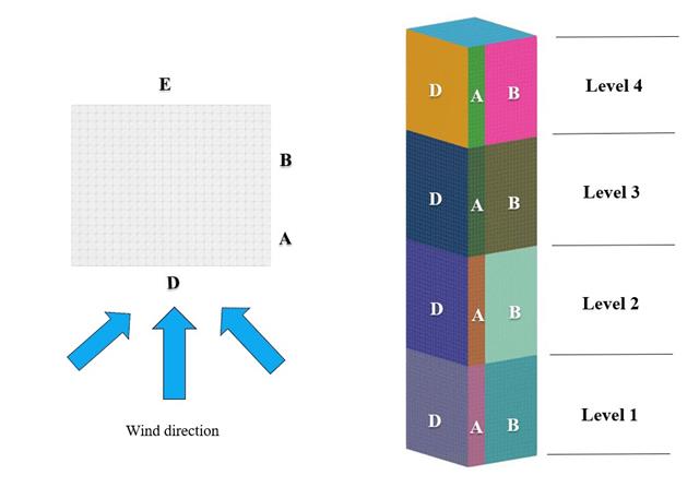
W bieżącym przykładzie walidacji badamy wartość parcia wiatru dla obu ogólnych projektów konstrukcyjnych (Cp,10 ) i okładzin lub elewacji (Cp,1 ) budynków na planie prostokąta zgodnie z EN 1991-1-4 [1]. Istnieją przypadki trójwymiarowe, o których więcej wyjaśnimy w następnej części.
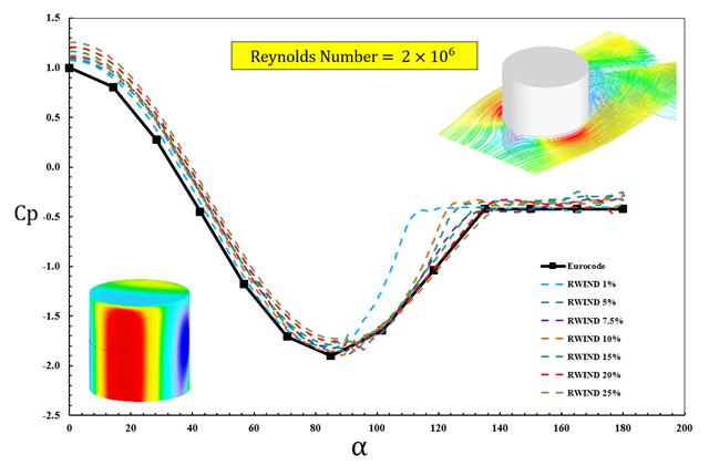
W dostępnych normach, takich jak EN 1991-1-4 [1], ASCE/SEI 7-16 i NBC 2015, przedstawiono parametry obciążenia wiatrem, takie jak współczynnik parcia wiatru (Cp ) dla podstawowe kształty. Ważne jest, jak szybciej i dokładniej obliczać parametry obciążenia wiatrem, niż pracować na czasochłonnych i czasami skomplikowanych wzorach w normach.
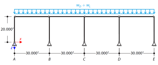
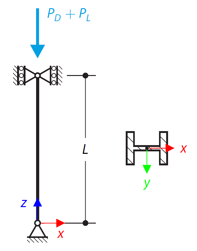
Za pomocą LRFD i ASD należy określić wymagane wytrzymałości i współczynniki długości efektywnej dla słupów z materiału ASTM A992 w ramie skręcania pokazanej na rysunku 1 dla maksymalnej kombinacji obciążeń grawitacyjnych.
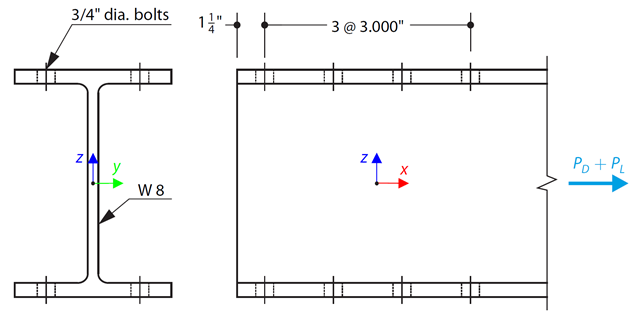
Wybrano pręt w kształcie litery W zgodny z ASTM A992 tak, aby przeniósł ciężar własny 30 000 kN i obciążenie rozciągające 90 000 kN. Sprawdź wytrzymałość pręta za pomocą LRFD i ASD.
Słup w kształcie litery W zgodny z normą ASTM A992 14x132 jest obciążony zadanymi osiowymi siłami ściskającymi. Słup jest przegubowy na górze i na dole w obu osiach. Należy określić, czy słup jest w stanie wytrzymać obciążenie pokazane na rysunku 1 na podstawie LRFD i ASD.
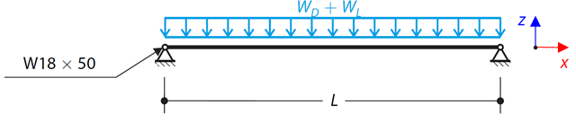
Rozważ belkę ASTM A992 W 18x50 dla stałych i równomiernych obciążeń stałych i ruchomych, jak pokazano na Rysunku 1. Pręt jest ograniczony do maksymalnej nominalnej głębokości wynoszącej 18 cali. Ugięcie pod obciążeniem użytkowym jest ograniczone do L/360. Belka jest swobodnie podparta i usztywniona. Sprawdź dostępną wytrzymałość na zginanie wybranej belki na podstawie LRFD i ASD.