27 Wyniki
Wyświetl wyniki:
Sortuj według:
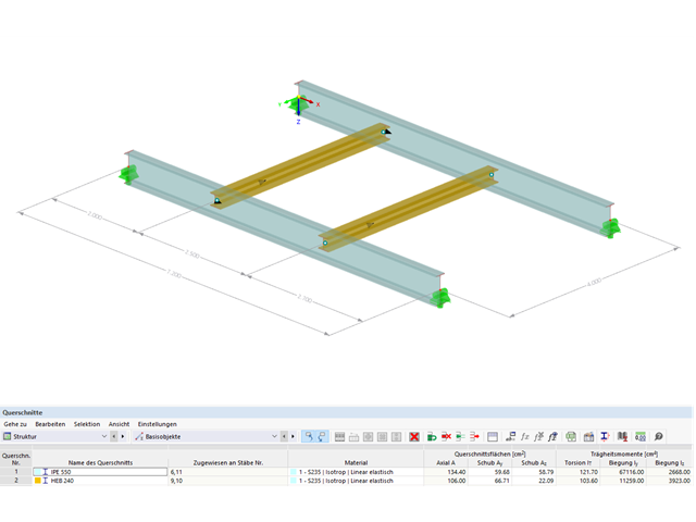
Przykład ten jest opisany w literaturze technicznej [1] jako przykład 9.5 oraz w [2] jako przykład 8.5. Dla podciągu należy przeprowadzić analizę zwichrzenia. Belka jest jednorodnym prętem konstrukcyjnym. Analizę stateczności można zatem przeprowadzić zgodnie z sekcją 6.3.2 normy DIN EN 1993-1-1. Ze względu na zginanie jednoosiowe, możliwe byłoby przeprowadzenie obliczeń również metodą ogólną według rozdz. 6.3.4. Ponadto, na wyidealizowanym modelu pręta należy zweryfikować wyznaczenie współczynnika obciążenia krytycznego w ramach w/w metody z modelem MES.

Wyboczenie giętno-skrętne (LTB) jest zjawiskiem, które występuje, gdy belka lub element konstrukcyjny są zginane, a pas ściskany nie jest wystarczająco podparty bocznie. Prowadzi to do kombinacji przemieszczenia bocznego i skręcenia. Jest to decydujący czynnik przy wymiarowaniu elementów konstrukcyjnych, zwłaszcza smukłych belek i dźwigarów.

Wymiarowanie prętów stalowych formowanych na zimno zgodnie z AISI S100-16 jest teraz dostępne w programie RFEM 6. Design can be accessed by selecting “AISC 360” as the standard in the Steel Design add-on. “AISI S100” is then automatically selected for the cold-formed design (Image 01).

Rozszerzenie Projektowanie konstrukcji aluminiowych dla RFEM 6 wymiaruje pręty aluminiowe ze względu na stan graniczny nośności i użytkowalności zgodnie z Eurokodem 9. Ponadto możliwe jest wymiarowanie zgodnie z ADM 2020 (norma amerykańska).
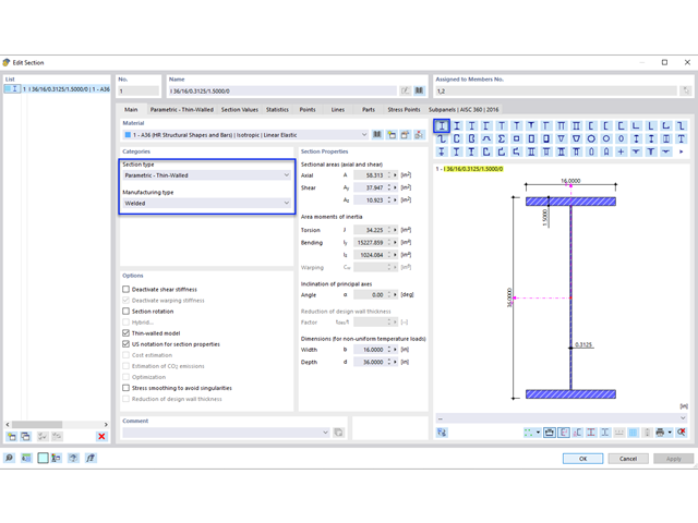
Blachownica to ekonomiczny wybór w przypadku konstrukcji o dużych rozpiętościach. I-section steel plate girder typically has a deep web to maximize its shear capacity and flange separation, yet thin web to minimize the self-weight. Due to its large height-to-thickness (h/tw) ratio, transverse stiffeners may be required to stiffen the slender web.
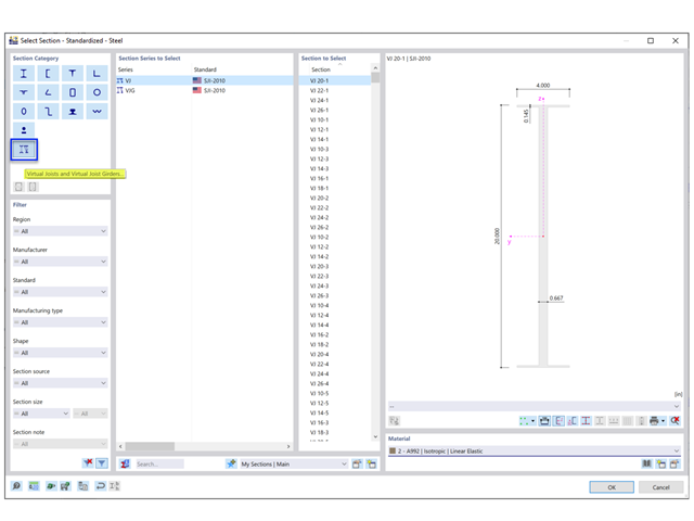
Steel Joist Institute (SJI) wcześniej opracował tabele wirtualnych belek nośnych w celu oszacowania właściwości przekroju dla belek stalowych z otwartym środnikiem. Te przekroje belek wirtualnych są scharakteryzowane jako równoważne belki o szerokich półkach, które są bardzo zbliżone do pola powierzchni pasa, efektywnego momentu bezwładności i ciężaru. Wirtualne belki nośne są również dostępne w bazie danych przekrojów w programach RFEM i RSTAB.
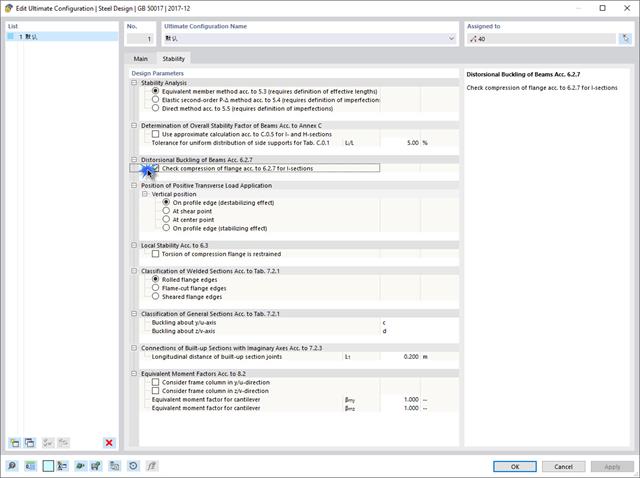
Jeżeli na górnej półce znajduje się płyta betonowa, działa ona jak podpora boczna (konstrukcja zespolona) i zapobiega problemom ze statecznością przy wyboczeniu skrętnym. Jeżeli moment zginający jest ujemny, dolna półka jest obciążona, a górna rozciągana. Jeżeli podparcie boczne nie jest wystarczające ze względu na sztywność środnika, kąt pomiędzy dolną półką a linią nacięcia środnika jest zmienny, przez co istnieje możliwość wystąpienia niestateczności wymiarowej dolnej półki.
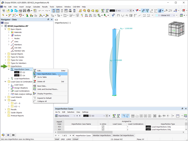
Imperfekcje w inżynierii konstrukcyjnej to odchylenia elementów konstrukcyjnych od ich idealnego kształtu, powstałe podczas produkcji. Są one często wykorzystywane w obliczeniach w celu określenia równowagi sił w elementach konstrukcyjnych w układzie odkształconym.

W tym artykule opisujemy, w jaki sposób można używać rozszerzenia Skręcanie skrępowane (7 stopni swobody) i Stateczność konstrukcji w celu uwzględnienia deplanacji przekroju jako dodatkowego stopnia swobody podczas analizy stateczności.

Sprawdzenie stateczności dla wymiarowania prętów zastępczych zgodnie z EN 1993-1-1, AISC 360, CSA S16 i innymi normami międzynarodowymi wymaga uwzględnienia długości obliczeniowej (tj. efektywnej długości prętów). W programie RFEM 6 długość efektywną można określić ręcznie, przypisując podpory węzłowe i współczynniki długości efektywnej lub, z drugiej strony, poprzez import z analizy stateczności. Obie opcje zostaną przedstawione w tym artykule poprzez określenie efektywnej długości słupa obramowanego na rysunku 1.