59 Wyniki
Wyświetl wyniki:
Sortuj według:

- Proponowane połączenie można zastosować do wszystkich wybranych węzłów w konstrukcji
- Położenie połączenia można zdefiniować w zakładce 'Główne' okna dialogowego rozszerzenia
- Obliczenia są przeprowadzane dla wszystkich połączeń w konstrukcji, a po zakończeniu obliczeń wyniki mogą być wyświetlane we wszystkich połączeniach
- W tabeli wyświetlane są wyniki dla poszczególnych połączeń, każde połączenie jest obliczane i może być zapisane osobno

Złożone połączenie belek poziomych ze słupem oraz połączenie stężeń ukośnych
Model połączenia został zamodelowany przy użyciu około 50 komponentów. Model został stworzony na podstawie rzeczywistego przykładu wykorzystania w konstrukcji.
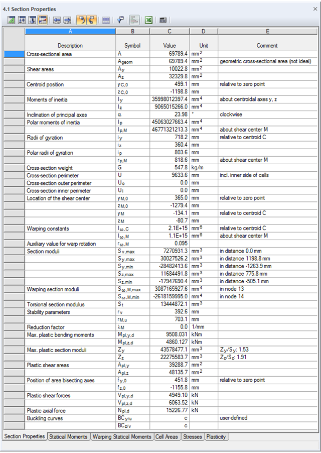
SHAPE-THIN określa charakterystyki przekroju i naprężenia dla przekrojów otwartych, zamkniętych, połączonych i niepołączonych.
- parametry przekroju
- Pole przekroju A
- Pole ścinane Ay, Az, Au i Av
- Położenie środka ciężkości yS, zS
- momenty pola 2 stopnie Iy, Iz, Iyz, Iu, Iv, Ip, Ip,M
- Promienie bezwładności iy, iz, iyz, iu, iv, ip, ip,M
- Nachylenie osi głównych α
- Ciężar przekroju G
- Średnica przekroju U
- momenty bezwładności przy skręcaniu stopnieIT , IT , IT,St.Venant, IT,Bredt, IT,s
- Położenie środka ścinania yM, zM
- Stałe deplanacji Iω,S, Iω,M or Iω,D dla utwierdzenia bocznego
- Max/min moduły przekroju Sy, Sz, Su, Sv, Sω,M z położeniami
- Promienie przekroju ru, rv, rM,u, rM,v
- Współczynnik redukcyjny λM
- Plastyczne charakterystyki przekroju
- Siła osiowa Npl,d
- Siły tnące Vpl,y,d, Vpl,z,d, Vpl,u,d, Vpl,v,d
- Momenty zginające Mpl,y,d, Mpl,z,d, Mpl,u,d, Mpl,v,d
- Moduły przekroju Zy, Zz, Zu, Zv
- Pola ścinania Apl,y, Apl,z, Apl,u, Apl,v
- Położenie osi powierzchni fu, fv,
- Wyświetlanie elipsy bezwładności
- Momenty statyczne pola Qu, Qv, Qy, Qz z położeniem maksimum i określeniem przebiegu ścinania
- Współrzędne wycinkowe ωM
- momenty bezwładności (wycinkowe powierzchnie) Sω,M
- Pola komórek Am zamkniętych przekrojów
- Naprężenia normalne σx wywołane siłą osiową, momentem zginającym i bimomentem deplanacji
- Naprężenia styczne τ od sił tnących oraz pierwotnych i drugorzędnych momentów skręcających
- Naprężenia zastępcze σv ze współczynnikiem dla naprężeń ścinających, który można dostosować do własnych potrzeb
- Stopnie wykorzystania odniesione do naprężeń granicznych
- Naprężenia dla krawędzi lub osi elementu
- Naprężenia w spoinach pachwinowych
- Charakterystyki przekrojów niepołączonych (rdzeń budynku wysokościowego, przekroje złożone)
- Siły tnące wywołane zginaniem i skręcaniem
- Obliczanie nośności plastycznej z określeniem współczynnika zwiększającego αpl
- Sprawdzenie stosunków c/t według metody el-el, el-pl lub pl-pl wg DIN 18800

W przypadku przekrojów prostokątnych zwykle można uzyskać bezpośrednie połączenie za pomocą spoin. W ten sam sposób można je jednak połączyć z innymi przekrojami. Ponadto inne elementy, takie jak blachy czołowe, pomagają w łączeniu przekrojów prostokątnych z innymi elementami konstrukcyjnymi.

Stalowe połączenia śrubowe z blachami węzłowymi na konstrukcji zadaszenia.
Pobierz model do analizy statyczno-wytrzymałościowej i otwórz go w programie RFEM 6, korzystając z rozszerzenia Połączenia stalowe.
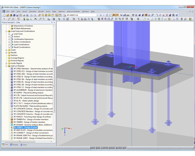
Główne funkcje wymiarowania połączeń są najpierw pogrupowane i wyświetlane wraz z podstawową geometrią połączenia w pierwszym oknie wyników. W pozostałych tabelach wyników można zobaczyć wszystkie istotne szczegóły obliczeń, takie jak nośność kotew, naprężenia w spoinach itp.
Wymiary, specyfikacje materiałowe i spoiny, które są istotne dla konstrukcji połączenia, są widoczne od razu i można je wydrukować. Połączenia można zwizualizować w module dodatkowym RF-/JOINTS Steel - Column Base lub w modelu RFEM/RSTAB.
Wszystkie grafiki mogą zostać dołączone do protokołu wydruku programu RFEM/RSTAB lub wydrukowane bezpośrednio. Dzięki skalowaniu wyników, możliwa jest optymalna kontrola wizualna już na etapie projektowania.

Wymiarowanie połączenia ramy o prętach zbieżnych i usztywnionych. Dla połączenia przeprowadzono analizę naprężeń i stateczności przy wyboczeniu. Aby wyświetlić wyniki dla wyboczenia, połączenie zostało przekształcone w osobny model.

Rozszerzenie Połączenia stalowe umożliwia wymiarowanie połączeń prętów o złożonych przekrojach. Ponadto można przeprowadzać obliczenia połączeń dla prawie wszystkich przekrojów cienkościennych z biblioteki programu RFEM.
Przejdź do filmuProgram wspiera Cię: Moduł określa siły w śrubach na podstawie modelu analitycznego ES i analizuje je automatycznie. Rozszerzenie przeprowadza obliczenia nośności śrub dla przypadków uszkodzeń, takich jak rozciąganie, ścinanie, docisk otworu i przebicie, zgodnie z normą i wyświetla w przejrzysty sposób wszystkie wymagane współczynniki.
Chcesz przeprowadzić wymiarowanie spoin? Spoiny są modelowane jako sprężysto-plastyczne elementy powierzchniowe, a ich naprężenia są odczytywane z modelu analitycznego ES. Kryterium plastyczności ma reprezentować zniszczenie zgodnie z AISC J2-4, J2-5 (wytrzymałość spoin) i J2-2 (wytrzymałość metalu podstawowego). Obliczenia można przeprowadzić z zastosowaniem częściowych współczynników bezpieczeństwa określonych w załączniku krajowym do normy EN 1993-1-8.
Płyty w połączeniu są wymiarowane w sposób plastyczny poprzez porównanie istniejącego odkształcenia plastycznego z dopuszczalnym odkształceniem plastycznym. Domyślne ustawienie wynosi 5% zgodnie z EN 1993-1-5, Załącznik C, ale można to zmienić według specyfikacji użytkownika, a także 5% dla AISC 360.
SHAPE-THIN określa wszystkie odpowiednie charakterystyki przekroju, wraz z plastycznymi siłami granicznymi i momentami. Nakładające się powierzchnie są uwzględniane w sposób realistyczny. Dla przekrojów utworzonych z różnych materiałów, SHAPE-THIN określa idealne charakterystyki przekroju w odniesieniu do materiału referencyjnego.
Oprócz analizy naprężeń w stanie sprężystym, można prowadzić również obliczenia w stanie plastycznym, zawierające interakcję sił wewnętrznych dla różnorodnych kształtów przekroju. Obliczenia interakcji plastycznej prowadzane są według metody Simplex. Podczas analizy naprężeń można wybrać różne teorie (Tresca lub von Mises).
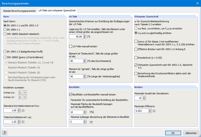
SHAPE-THIN przeprowadza klasyfikację przekroju zgodnie z EN 1993-1-1 i EN 1999-1-1. W przypadku przekrojów stalowych o przekroju 4, program określa szerokości efektywne dla płyt usztywnionych lub nieusztywnionych, zgodnie z EN 1993-1-1 i EN 1993-1-5. W przypadku przekrojów aluminiowych o przekroju klasy 4, program oblicza grubości efektywne zgodnie z EN 1999-1-1.
Opcjonalnie SHAPE-THIN sprawdza wartości graniczne c/t zgodnie z metodami obliczeniowymi el-el, el-pl lub pl-pl zgodnie z DIN 18800. Przekrój jest klasyfikowany według danej kombinacji sił wewnętrznych.