36 Wyniki
Wyświetl wyniki:
Sortuj według:

- 002452
- Ogólne informacje
- Projektowanie konstrukcji aluminiowych RFEM 6
- Projektowanie konstrukcji aluminiowych RSTAB 9
Program wykonuje za Ciebie dużo pracy. Na przykład kombinacje obciążeń lub wyników, które są niezbędne dla stanu granicznego użytkowalności, są generowane i obliczane w programie RFEM/RSTAB. Te sytuacje obliczeniowe można wybrać w rozszerzeniu Aluminium Design w celu przeprowadzenia analizy ugięcia. W zależności od wprowadzonej przechyłki i wybranego układu odniesienia program określa obliczone wartości deformacji w każdym punkcie pręta. Następnie są one porównywane z wartościami granicznymi.
W konfiguracji Stan graniczny użytkowalności można ustawić wartość graniczną, która ma być obserwowana dla odkształcenia dla każdego komponentu z osobna. Jako dopuszczalną wartość graniczną definiuje się maksymalne odkształcenie w zależności od długości odniesienia. Definiując podpory obliczeniowe, można segmentować komponenty. W ten sposób można automatycznie określić odpowiednią długość odniesienia dla każdego kierunku obliczeń.
To nie wszystko. W oparciu o położenie przypisanych podpór obliczeniowych program automatycznie umożliwia rozróżnienie belek i belek wspornikowych. W ten sposób określana jest odpowiednio wartość graniczna.

- 002453
- Ogólne informacje
- Projektowanie konstrukcji aluminiowych RFEM 6
- Projektowanie konstrukcji aluminiowych RSTAB 9
Obliczenia w stanie granicznym użytkowalności można znaleźć w tabelach wyników w rozszerzeniu do obliczeń dla aluminium. Są tam już w pełni zintegrowane. Istnieje możliwość uzyskania wyników obliczeń w każdym punkcie wymiarowanych prętów ze wszystkimi szczegółami. Można również użyć grafiki z wynikami współczynników obliczeniowych.
W razie potrzeby wszystkie tabele wyników i grafiki można uwzględnić jako część wyników obliczeń aluminium w globalnym raporcie wydruku programu RFEM/RSTAB. Program RFEM/RSTAB umożliwia również wyświetlanie i dokumentowanie wartości deformacji całej konstrukcji niezależnie od tego, czy jest to moduł dodatkowy.

Budowanie kamień na kamieniu ma długą tradycję w budownictwie. Rozszerzenie Projektowanie konstrukcji murowych dla RFEM umożliwia wymiarowanie konstrukcji murowych przy użyciu metody elementów skończonych. Rozszerzenie powstało w ramach projektu badawczego DDMaS - Digitalizacja wymiarowania konstrukcji murowych. Model materiałowy przedstawia nieliniowe zachowanie połączenia cegła-zaprawa w postaci modelowania w skali makro. Chcesz dowiedzieć się więcej?
- 002456
- Ogólne informacje
- Projektowanie konstrukcji aluminiowych RFEM 6
- Projektowanie konstrukcji aluminiowych RSTAB 9
Przy obliczaniu granicznego ugięcia należy wziąć pod uwagę określone długości odniesienia. Te długości odniesienia i sprawdzane segmenty można definiować niezależnie od siebie, w zależności od kierunku. W tym celu należy zdefiniować podpory obliczeniowe w węzłach pośrednich pręta i przypisać je do odpowiedniego kierunku dla analizy deformacji. Tworzy to segmenty, w których można uwzględnić przechyłkę dla każdego kierunku i segmentu.

- 002454
- Ogólne informacje
- Projektowanie konstrukcji aluminiowych RFEM 6
- Projektowanie konstrukcji aluminiowych RSTAB 9
Czy bardzo to lubisz? My też! Z tego powodu wszystkie sprawdzenia dotyczące normy projektowej są wyświetlane w przejrzysty sposób. Dla każdej kontroli obliczeń należy zdefiniować kryterium wykorzystania. Szczegóły obliczeń, w których wartości wejściowe, wyniki pośrednie i wyniki końcowe są uporządkowane w sposób uporządkowany, są dostępne dla każdej kontroli obliczeń. Proces obliczeń wraz ze wszystkimi wzorami, normami i wynikami znajduje się w oknie informacyjnym, w którym wyświetlane są szczegóły obliczeń.

- 002464
- Wyniki
- Projektowanie konstrukcji aluminiowych RFEM 6
- Projektowanie konstrukcji aluminiowych RSTAB 9
Jak zwykle, wprowadzasz układ i obliczasz siły wewnętrzne w programach RFEM i RSTAB. Masz nieograniczony dostęp do obszernych bibliotek materiałów i przekrojów. Czy wiesz, że za pomocą programu RSECTION można tworzyć przekroje ogólne? Oszczędza to dużo pracy.
Nie bój się'dodatkowych okien i chaosu przy wprowadzaniu danych! Dzieje się tak, ponieważ wymiarowanie aluminium jest w pełni zintegrowane z programami głównymi i automatycznie uwzględnia konstrukcję oraz istniejące wyniki obliczeń. Dalsze dane wejściowe dla obliczeń aluminium, takie jak długości efektywne, redukcje przekroju lub parametry obliczeniowe, można przypisać bezpośrednio do projektowanych obiektów. W wielu miejscach programu najlepiej jest użyć funkcji [Wskaż] do wyboru grafiki - w prosty i efektywny sposób.

- 002460
- Ogólne informacje
- Projektowanie konstrukcji aluminiowych RFEM 6
- Projektowanie konstrukcji aluminiowych RSTAB 9
Należy upewnić się, że zdefiniowanie długości efektywnych w aluminiowym module dodatkowym jest warunkiem niezbędnym do przeprowadzenia analizy stateczności. W tym celu w oknie dialogowym należy zdefiniować podpory węzłowe i współczynniki długości efektywnej. Czy chcesz przejrzyście udokumentować podpory węzłowe i wynikające z nich segmenty wraz z powiązanym współczynnikiem długości efektywnej? W celu sprawdzenia wprowadzonych danych najlepiej jest użyć prezentacji graficznej w oknie roboczym programu RFEM/RSTAB. Oznacza to, że możesz zrozumieć projekt w dowolnym momencie i bez większego wysiłku.

- 002141
- Ogólne informacje
- Projektowanie konstrukcji aluminiowych RFEM 6
- Projektowanie konstrukcji aluminiowych RSTAB 9
- Wymiarowanie elementów rozciąganych, ściskanych, zginanych, ścinanych, skręcanych i poddanych połączonemu działaniu tych sił wewnętrznych
- Obliczanie rozciągania z uwzględnieniem zredukowanej powierzchni przekroju (np. osłabienie z uwagi na otwory)
- Automatyczna klasyfikacja przekrojów w celu sprawdzenia wyboczenia lokalnego
- Siły wewnętrzne z obliczeń ze skręcaniem skrępowanym (7 stopni swobody) są uwzględniane w kontroli naprężeń zastępczych (obecnie nie dla normy ADM 2020)
- Wymiarowanie przekrojów klasy 4 o właściwościach przekroju efektywnego zgodnie z EN 1999-1-1 (dla przekrojów RSECTION wymagane są licencje dla przekrojów RSECTION i "Przekroje efektywne")
- Sprawdzenie wyboczenia przy ścinaniu z uwzględnieniem usztywnień poprzecznych

- 002451
- Ogólne informacje
- Projektowanie konstrukcji aluminiowych RFEM 6
- Projektowanie konstrukcji aluminiowych RSTAB 9
- Obliczanie ugięć i porównanie z normatywnymi lub ręcznie dostosowanymi wartościami granicznymi
- Uwzględnienie wygięcia wstępnego w analizie ugięcia
- W zależności od typu sytuacji obliczeniowej możliwe są różne wartości graniczne
- Ręczne dostosowywanie długości odniesienia i segmentacji według kierunku
- Obliczenia ugięć w odniesieniu do konstrukcji wyjściowej lub konstrukcji odkształconej
- Dalsze szczegółowe weryfikacje w zależności od wybranej normy obliczeniowej (np. weryfikacja drgań zgodnie z EN 1999-1-1, 7.2.3)
- Graficzne wyświetlanie wyników zintegrowane w programie RFEM/RSTAB, na przykład stopień wykorzystania wartości granicznej, odkształcenie lub ugięcie
- Pełna integracja wyników z raportem RFEM/RSTAB
- 002455
- Ogólne informacje
- Projektowanie konstrukcji aluminiowych RFEM 6
- Projektowanie konstrukcji aluminiowych RSTAB 9
Weryfikacje można znaleźć w rozszerzeniu dotyczącym konstrukcji aluminiowych w postaci przejrzystych tabel. Można również przedstawić graficznie rozwój współczynników obliczeniowych. Rozbudowane opcje filtrowania są dostępne zarówno w tabeli, jak i w danych wyjściowych graficznych. W ten sposób program może wyświetlać żądane obliczenia według stanu granicznego lub typu obliczeniowego.

- 002140
- Ogólne informacje
- Projektowanie konstrukcji aluminiowych RFEM 6
- Projektowanie konstrukcji aluminiowych RSTAB 9
- Szeroki wybór dostępnych przekrojów, takich jak dwuteowniki walcowane; ceowniki; teowniki; kątowniki; profile zamknięte prostokątne i okrągłe; pręty okrągłe; przekroje symetryczne i niesymetryczne, parametryczne przekroje dwuteowe, teowe, kątowniki; przekroje złożone (przydatność do obliczeń zależy od wybranej normy)
- Wymiarowanie ogólnych przekrojów RSECTION (w zależności od formatów obliczeniowych dostępnych w odpowiedniej normie); na przykład obliczanie naprężeń zastępczych
- Wymiarowanie prętów o zbieżnym przekroju (metoda zależna od normy)
- Możliwe jest dostosowanie istotnych współczynników obliczeniowych i parametrów normowych
- Elastyczność dzięki szczegółowym opcjom ustawień dla podstawy i zakresu obliczeń
- Szybkie i przejrzyste wyświetlanie wyników dla globalnej oceny ich rozkładu na konstrukcji po zakończeniu obliczeń
- Szczegółowe wyniki obliczeń i niezbędne wzory (jasna i łatwa do zweryfikowania ścieżka wyników)
- Przejrzyste zestawienie wyników w formie numerycznej w stosownych oknach oraz możliwość ich graficznego przedstawienia na konstrukcji
- Integracja wyników z protokołem wydruku programu RFEM/RSTAB

- 002720
- Ogólne informacje
- Analiza stateczności konstrukcji RFEM 6
- Analiza stateczności konstrukcji RSTAB 9
Stosując modalny współczynnik istotności (MRF) można ocenić, w jakim stopniu poszczególne elementy konstrukcyjne przyczyniają się do powstania rzeczywistego kształtu wyboczenia. Obliczenia opierają się na energii względnego odkształcenia sprężystego każdego pojedynczego pręta.
Dzięki MRF można rozróżnić lokalne i globalne kształty wyboczenia. Jeżeli kilka prętów ma znaczny MRF (np. > 20%), bardzo prawdopodobna jest niestateczność całej konstrukcji lub jej części. Jeżeli jednak suma wszystkich MRF dla kształtu drgań wynosi około 100%, należy spodziewać się lokalnego problemu ze statecznością (np. wyboczenia pojedynczego pręta).
Ponadto MRF może być wykorzystany do określenia obciążeń krytycznych i równoważnych długości wyboczeniowych poszczególnych prętów (np. do analizy stateczności). Kształty wyboczenia, dla których dany pręt ma małe wartości MRF (np. <20%), mogą zostać w tym kontekście pominięte.
MRF jest wyświetlany według kształtów wyboczenia w tabeli wyników w sekcji Analiza stateczności --> Wyniki według prętów --> Długości efektywne i obciążenia krytyczne.
- 002073
- Ogólne informacje
- Analiza stateczności konstrukcji RFEM 6
- Analiza stateczności konstrukcji RSTAB 9
- Obliczanie modeli składających się z elementów prętowych, powłokowych i bryłowych
- Nieliniowa analiza stateczności
- Możliwość uwzględniania sił osiowych od wstępnego sprężenia
- Cztery dostępne solvery do rozwiązywania równań dla efektywnego obliczania różnych modeli konstrukcyjnych
- Opcjonalne uwzględnianie zmian w sztywności w programie RFEM/RSTAB
- Wyszukiwanie postaci wyboczeniowych o krytycznym mnożniku obciążenia większym niż zadany przez użytkownika (metoda "przesunięcia")
- Możliwość określania wektorów własnych dla modeli niestatecznych (w celu zidentyfikowania przyczyny niestateczności)
- Wizualizacja postaci niestateczności
- Podstawa określania imperfekcji

- Definiowanie naprężeń na przykładzie sprężysto-plastycznego modelu materiałowego
- Wymiarowanie murowych konstrukcji tarczowych na ściskanie i ścinanie na modelu budynku lub na pojedynczym modelu
- Automatyczne określanie sztywności przegubu ściana-płyta
- Obszerna baza danych materiałów o prawie wszystkich kombinacjach kamienia i zapraw dostępnych na rynku austriackim (asortyment jest stale poszerzany, również dla innych krajów)
- Automatyczne określanie wartości materiałów zgodnie z Eurokodem 6 (ÖN EN 1996‑X)
- Możliwość przeprowadzenia analizy pushover

Konstrukcję wprowadza się i modeluje się bezpośrednio w programie RFEM. Model materiałowy muru można połączyć ze wszystkimi popularnymi rozszerzeniami dla programu RFEM. Umożliwia to projektowanie całych modeli budynków w połączeniu z murem.
Program automatycznie określa wszystkie parametry wymagane do obliczeń na podstawie wprowadzonych danych materiału. Następnie generowane są krzywe naprężenie-odkształcenie dla każdego elementu skończonego.

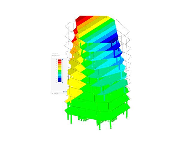
Proces znajdowania kształtu tworzy model konstrukcyjny z aktywnymi siłami w "przypadku obciążenia sprężonego" Ten przypadek obciążenia pokazuje przemieszczenie od początkowego położenia wejściowego do ustalonej geometrii w wynikach deformacji. W wynikach opartych na sile lub naprężeniach (siły wewnętrzne prętów i powierzchni, naprężenia w bryłach, ciśnienia gazu itp.) określany jest stan w celu zachowania znalezionej formy. Do analizy kształtu geometrycznego program oferuje dwuwymiarowy wykres konturowy z przedstawieniem wysokości bezwzględnej i wykresem nachylenia do wizualizacji sytuacji na zboczu.
Teraz przeprowadzane są dalsze obliczenia i analiza statyczno-wytrzymałościowa całego modelu. W tym celu program przenosi geometrię zorientowaną na kształt wraz z odkształceniami zależnymi od elementów do uniwersalnego stanu początkowego. Można go teraz używać w przypadkach obciążeń i kombinacjach obciążeń.

- 002074
- Ogólne informacje
- Analiza stateczności konstrukcji RFEM 6
- Analiza stateczności konstrukcji RSTAB 9
Jeżeli w programie istnieje przypadek obciążenia lub kombinacja obciążeń, obliczenia stateczności są aktywowane. Można zdefiniować inny przypadek obciążenia, na przykład w celu uwzględnienia naprężenia początkowego.
W tym celu należy określić, czy ma zostać przeprowadzona analiza liniowa czy nieliniowa. W zależności od przypadku zastosowania, można wybrać bezpośrednią metodę obliczeniową, taką jak metoda Lanczosa lub metoda iteracji ICG. Pręty niezintegrowane z powierzchniami są zazwyczaj wyświetlane jako elementy prętowe z dwoma węzłami ES. W przypadku zastosowania takich elementów program nie może określić wyboczenia lokalnego pojedynczych prętów. Z tego względu'istnieje możliwość automatycznego dzielenia prętów.
- 002465
- Wyniki
- Projektowanie konstrukcji aluminiowych RFEM 6
- Projektowanie konstrukcji aluminiowych RSTAB 9
Czy projekt zakończył się sukcesem? Bardzo dobrze, teraz zaczyna się część zrelaksowana. Ponieważ program przedstawia przeprowadzone weryfikacje w formie tabelarycznej. Można wyświetlić szczegółowe informacje o wszystkich wynikach. Dzięki przejrzyście przedstawionym wzorom weryfikacyjnym można bez problemu zrozumieć wyniki. W oprogramowaniu Dlubal nie występuje efekt czarnej skrzynki.
Kontrole są przeprowadzane we wszystkich istotnych punktach prętów i wyświetlane graficznie jako profil wyników. Bardziej szczegółowe grafiki można znaleźć w wynikach wyszukiwania. Obejmuje to na przykład profil naprężenia w przekroju lub kształt drgań własnych.
Wszystkie dane wejściowe i wyniki są częścią protokołu wydruku programu RFEM/RSTAB. Dla poszczególnych obliczeń można wybrać zawartość raportu i żądaną głębokość danych wyjściowych.
- 002463
- Ogólne informacje
- Projektowanie konstrukcji aluminiowych RFEM 6
- Projektowanie konstrukcji aluminiowych RSTAB 9
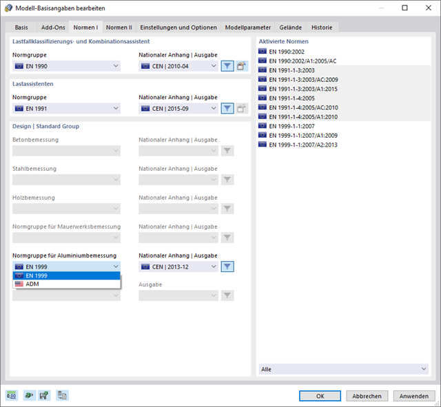
W przypadku obliczeń zgodnie z Eurokodem 9, można znaleźć parametry zintegrowanych załączników krajowych dla następujących krajów:
-
 DIN EN 1999-1-1/NA:2021-03 (Niemcy)
 -
 ÖNORM EN 1999-1-1/NA:2017-11 (Austria)
 -
 SN EN 1999-1-1/NA:2015-01 (Szwajcaria)
 -
 BDS EN 1999-1-1/NA:2014-05 (Bułgaria)
 -
 BS EN 1999-1-1/NA:2014-03 (Wielka Brytania)
 -
 CEN 1999-1-1/2013-12 (Unia Europejska)
 -
 CYS EN 1999-1-1/NA:2019-08 (Cypr)
 -
 CZE EN 1999-1-1/NA:2015-09 (Republika Czeska)
 -
 DS EN 1999-1-1/NA:2019-09 (Dania)
 -
 ELOT EN 1999-1-1/NA:2013-12 (Grecja)
 -
 EVS EN 1999-1-1/NA:2014-01 (Estonia)
 -
 HRN EN 1999-1-1/NA:2015-02 (Chorwacja)
 -
 I S. EN 1999-1-1/NA:2015-01 (Irlandia)
 -
 ILNAS EN 1999-1-1/NA:2013-12 (Luksemburg)
 -
 IST EN 1999-1-1/NA:2014-03 (Islandia)
 -
 LST EN 1999-1-1/NA:2014-03 (Litwa)
 -
 LVS EN 1999-1-1/NA:2015-01 (Łotwa)
 -
 MSZ EN 1999-1-1/NA:2014-04 (Węgry)
 -
 NBN EN 1999-1-1/NA:2014-01 (Belgia)
 -
 NEN EN 1999-1-1/NA:2014-01 (Holandia)
 -
 NF EN 1999-1-1/NA:2016-07 (Francja)
 -
 NP EN 1999-1-1/NA:2014-11 (Portugalia)
 -
 NS EN 1999-1-1/NA:2014-04 (Norwegia)
 -
 PN EN 1999-1-1/NA:2014-05 (Polska)
 -
 SFS EN 1999-1-1/NA:2018-01 (Finlandia)
 -
 SIST EN 1999-1-1/NA:2014-05 (Słowenia)
 -
 SR EN 1999-1-1/NA:2015-01 (Rumunia)
 -
 SS EN 1999-1-1/NA:2013-12 (Szwecja)
 -
 STN EN 1999-1-1/NA:2014-05 (Słowacja)
 -
 TKP EN 1999-1-1/NA:2010-01 (Białoruś)
 -
 UNE EN 1999-1-1/NA:2014-01 (Hiszpania)
 -
 UNI EN 1999-1-1/NA:2014-02 (Włochy)

- 002458
- Ogólne informacje
- Projektowanie konstrukcji aluminiowych RFEM 6
- Projektowanie konstrukcji aluminiowych RSTAB 9
Wiesz na pewno, że podczas łączenia elementów rozciąganych za pomocą połączeń śrubowych należy wziąć pod uwagę osłabienie przekroju spowodowane otworami na śruby. Programy do analizy statyczno-wytrzymałościowej również mają na to rozwiązanie. W rozszerzeniu Aluminium Design można wprowadzić lokalną redukcję przekroju pręta. Redukcję przekroju należy wprowadzić jako wartość bezwzględną lub jako procent powierzchni całkowitej.