50 Wyniki
Wyświetl wyniki:
Sortuj według:

W celu obliczenia odporności ogniowej powierzchni drewnianych można wyświetlić wykres zwęglania w zależności od czasu trwania pożaru.
Wykres ten można również wydrukować w raporcie.

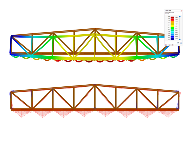
Dla każdego przypadku obciążenia można wyświetlić odkształcenia w czasie końcowym.
Wyniki te są również dokumentowane w protokole wydruku programów RFEM i RSTAB. Zawartość protokołu i jego zakres można wybrać specjalnie dla poszczególnych warunków projektowych.

Budowanie kamień na kamieniu ma długą tradycję w budownictwie. Rozszerzenie Projektowanie konstrukcji murowych dla RFEM umożliwia wymiarowanie konstrukcji murowych przy użyciu metody elementów skończonych. Rozszerzenie powstało w ramach projektu badawczego DDMaS - Digitalizacja wymiarowania konstrukcji murowych. Model materiałowy przedstawia nieliniowe zachowanie połączenia cegła-zaprawa w postaci modelowania w skali makro. Chcesz dowiedzieć się więcej?

W przypadku analizy spektrum odpowiedzi modeli budynków można wyświetlić współczynniki wrażliwości dla kierunków poziomych według kondygnacji.
Dzięki tym kluczowym wartościom można zinterpretować wrażliwość na efekty stateczności.

- 002687
- Ogólne informacje
- Projektowanie konstrukcji drewnianych RFEM 6
- Projektowanie konstrukcji drewnianych RSTAB 9
Rozszerzenie Projektowanie konstrukcji drewnianych dla programu RFEM 6/RSTAB 9 ma wiele zastosowań i łączy w sobie wiele dodatkowych elementów. [*S16332764*] Rozszerzenie Wymiarowanie drewna dla RFEM 6
- 002371
- Ogólne informacje
- Projektowanie konstrukcji drewnianych RFEM 6
- Projektowanie konstrukcji drewnianych RSTAB 9
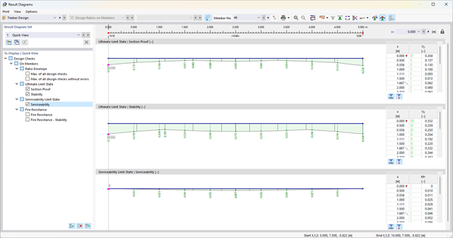
Obliczenia stanu granicznego użytkowalności są w pełni zintegrowane z tabelami wyników w rozszerzeniu Projektowanie konstrukcji drewnianych. Aby sprawdzić wyniki obliczeń, można otworzyć program i wyświetlić wyniki ze wszystkimi szczegółami w każdym miejscu obliczanych prętów. Ponadto dostępne są grafiki z wykresami wyników i stopni wykorzystania.
Cechą szczególną jest to, że Wszystkie tabele wyników i grafiki można zintegrować z globalnym protokołem wydruku programu RFEM/RSTAB jako część wyników wymiarowania drewna. Odkształcenia całej konstrukcji można również wyświetlać i dokumentować w ramach funkcji programu RFEM/RSTAB. Ta funkcja jest niezależna od rozszerzenia.
- 002382
- Ogólne informacje
- Projektowanie konstrukcji drewnianych RFEM 6
- Projektowanie konstrukcji drewnianych RSTAB 9
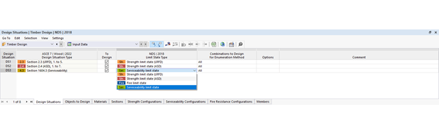
Nadal szukasz projektu? Kontrole obliczeń są dostępne w formie tabelarycznej w rozszerzeniu Projektowanie konstrukcji drewnianych. Program może również przedstawić rozkład stopni wykorzystania w sposób graficzny. W tabeli oraz w wynikach graficznych dostępne są obszerne opcje filtrowania, umożliwiające wyświetlanie żądanych warunków projektowych według stanu granicznego lub typu obliczeniowego.
- 002370
- Ogólne informacje
- Projektowanie konstrukcji drewnianych RFEM 6
- Projektowanie konstrukcji drewnianych RSTAB 9
Za wygenerowanie i obliczenie kombinacji obciążeń i wyników wymaganych dla stanu granicznego użytkowalności odpowiada program RFEM/RSTAB. W rozszerzeniu Projektowanie konstrukcji drewnianych można wybrać sytuacje obliczeniowe do analizy ugięć. Obliczone wartości odkształceń są następnie określane w każdym miejscu pręta, w zależności od określonego wygięcia wstępnego i układu odniesienia, a następnie porównywane z wartościami granicznymi.
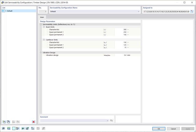
Wartość graniczną deformacji można określić indywidualnie dla każdego elementu konstrukcyjnego w Konfiguracja stanu granicznego użytkowalności. W takim przypadku maksymalne odkształcenie nie powinno przekraczać dopuszczalnej wartości granicznej, zależnej od długości odniesienia. Podczas definiowania podpór obliczeniowych można podzielić komponenty na segmenty. Umożliwia to automatyczne określenie odpowiedniej długości odniesienia dla każdego kierunku obliczeń.
Na podstawie położenia przypisanych podpór obliczeniowych program automatycznie określa różnicę między belkami a wspornikami. W ten sposób można mieć pewność, że wartość graniczna zostanie odpowiednio określona.

- 002133
- Ogólne informacje
- Projektowanie konstrukcji drewnianych RFEM 6
- Projektowanie konstrukcji drewnianych RSTAB 9
- Szeroki wybór przekrojów, takich jak przekroje prostokątne, kwadratowe, teowe, okrągłe, złożone, nieregularne przekroje parametryczne i wiele innych (przydatność do obliczeń zależy od wybranej normy)
- Wymiarowanie drewna klejonego krzyżowo (CLT)
- Wymiarowanie materiałów drewnopochodnych i drewna klejonego warstwowo zgodnie z EC 5
- Wymiarowanie prętów o zmiennym przekroju (metoda zgodna z normą)
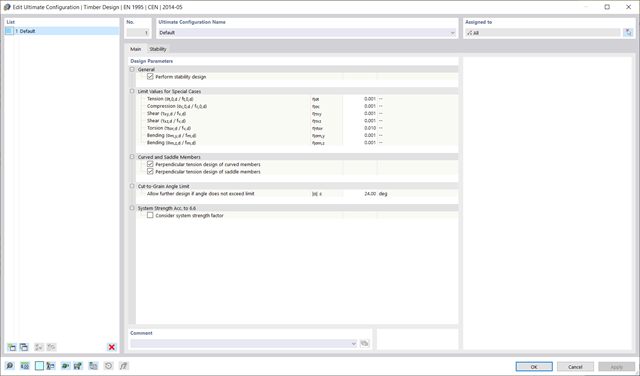
- Możliwe jest dostosowanie istotnych współczynników obliczeniowych i parametrów normowych
- Elastyczność dzięki szczegółowym opcjom ustawień dla podstawy i zakresu obliczeń
- Szybkie i przejrzyste wyświetlanie wyników dla globalnej oceny ich rozkładu na konstrukcji po zakończeniu obliczeń
- Szczegółowe wyniki obliczeń i niezbędne wzory (jasna i łatwa do zweryfikowania ścieżka wyników)
- Przejrzyste zestawienie wyników w formie numerycznej w stosownych oknach oraz możliwość ich graficznego przedstawienia na konstrukcji
- Integracja wyników z protokołem wydruku programu RFEM/RSTAB

- 002372
- Ogólne informacje
- Projektowanie konstrukcji drewnianych RFEM 6
- Projektowanie konstrukcji drewnianych RSTAB 9
- Dowolna definicja czasu zwęglania
- W przypadku konstrukcji powierzchniowych (drewno klejone krzyżowo) można obliczyć z przyczepnością lub bez
- Bezpłatna, zdefiniowana przez użytkownika specyfikacja parametrów pożaru
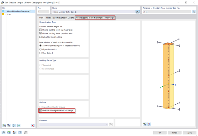
- Uwzględnienie różnych długości efektywnych do obliczania odporności ogniowej
- Opcjonalne obliczenia dla 'ściskania w poprzek włókien'
- Zintegrowane z RFEM/RSTAB graficzne wyświetlanie wyników, np. B. Stopień wykorzystania
- Pełna integracja wyników z protokołem wydruku programu RFEM/RSTAB

Istnieje możliwość wymiarowania powierzchni z uwagi na warunki pożarowe przy użyciu metody zredukowanego przekroju. Redukcja jest stosowana na grubości powierzchni. Kontrolę obliczeń można przeprowadzić dla wszystkich materiałów drewnianych, które są dopuszczone dla obliczeń.
W przypadku drewna klejonego krzyżowo, w zależności od rodzaju kleju, można wybrać, czy możliwe jest odpadanie poszczególnych zwęglonych części warstwy, a tym samym, czy można spodziewać się zwiększonego zwęglenia w niektórych obszarach warstwy.
Dzięki rozszerzeniu Analiza historii czasowej (TDA) można uwzględnić zmienne w czasie zachowanie materiału w przypadku prętów i powierzchni. Długotrwałe efekty, takie jak pełzanie, skurcz i starzenie, mogą wpływać na rozkład sił wewnętrznych, w zależności od konstrukcji. Darauf bereiten Sie sich mit diesem Add-On optimal vor.
- 002386
- Obliczenia
- Projektowanie konstrukcji drewnianych RFEM 6
- Projektowanie konstrukcji drewnianych RSTAB 9
Układ konstrukcyjny można wprowadzić i obliczyć siły wewnętrzne w programach RFEM i RSTAB. Użytkownik ma pełny dostęp do obszernych bibliotek materiałów i przekrojów.
Projektowanie konstrukcji drewnianych jest w pełni zintegrowane z programami głównymi. Jednocześnie automatycznie uwzględnia konstrukcję i dostępne wyniki obliczeń. Do wymiarowanych obiektów można przydzielić dodatkowe dane dla wymiarowania drewna, takie jak długości efektywne, redukcje przekroju lub parametry obliczeniowe. Elementy można wybrać graficznie w wielu miejscach programu za pomocą funkcji [Wybrać].

- 002383
- Ogólne informacje
- Projektowanie konstrukcji drewnianych RFEM 6
- Projektowanie konstrukcji drewnianych RSTAB 9
Masz pytania dotyczące programu? W zależności od kierunku można indywidualnie zdefiniować długości odniesienia, które zostaną uwzględnione podczas obliczeń wartości granicznej ugięcia oraz które segmenty mają zostać sprawdzone. W tym celu należy zdefiniować podpory obliczeniowe w węzłach pośrednich pręta i przydzielić je do odpowiedniego kierunku na potrzeby analizy odkształceń. W segmentach wynikowych można również zdefiniować wygięcie wstępne dla każdego kierunku i segmentu.
_ENG.png?mw=640&hash=1053c9bef400e9f5361c9c3278f76a272fcc4ddf)
Czy aktywowałeś rozszerzenie Analiza historii czasowej (TDA)? Dobrze, teraz można dodawać dane czasowe do przypadków obciążeń. Po zdefiniowaniu początku i końca obciążenia, uwzględniany jest wpływ pełzania na końcu obciążenia. Program umożliwia modelowanie efektów pełzania w konstrukcjach szkieletowych i kratowych wykonanych z betonu zbrojonego.
W tym przypadku obliczenia są przeprowadzane nieliniowo zgodnie z modelem reologicznym (model Kelvina i Maxwella).
Czy obliczenia zakończyły się pomyślnie? Wyznaczone siły wewnętrzne można teraz wyświetlić w tabelach i grafice, a także uwzględnić w obliczeniach.

Oprogramowanie do analizy statyczno-wytrzymałościowej firmy Dlubal wykonuje wiele pracy za Ciebie. Program sugeruje zgodnie z regułami parametry wejściowe, istotne dla wybranych norm. Ponadto można ręcznie wprowadzić spektra odpowiedzi.
Przypadki obciążeń typu Analiza spektrum odpowiedzi określają kierunek, w którym działają spektra odpowiedzi oraz które wartości własne konstrukcji są istotne dla analizy. W ustawieniach analizy spektralnej można zdefiniować szczegóły dotyczące reguł kombinacji, tłumienia (jeśli ma zastosowanie) i przyspieszenia okresu zerowego (ZPA).
- 002369
- Ogólne informacje
- Projektowanie konstrukcji drewnianych RFEM 6
- Projektowanie konstrukcji drewnianych RSTAB 9
- Obliczanie ugięć i porównanie z normatywnymi lub ręcznie dostosowanymi wartościami granicznymi
- Uwzględnienie wygięcia wstępnego w analizie ugięcia
- W zależności od typu sytuacji obliczeniowej możliwe są różne wartości graniczne
- Ręczne dostosowywanie długości odniesienia i segmentacji według kierunku
- Obliczanie ugięć w odniesieniu do konstrukcji początkowej lub do konstrukcji odkształconej
- Automatyczne uwzględnienie odkształceń zależnych od czasu poprzez zwiększenie obciążenia o współczynnik pełzania (może być również zdefiniowany przez użytkownika po stronie sztywności)
- Uproszczone obliczenia drgań
- Graficzne wyświetlanie wyników zintegrowane z RFEM/RSTAB; na przykład stopień wykorzystania wartości granicznej, odkształcenie lub ugięcie
- Pełna integracja wyników z protokołem wydruku programu RFEM/RSTAB
- 002387
- Obliczenia
- Projektowanie konstrukcji drewnianych RFEM 6
- Projektowanie konstrukcji drewnianych RSTAB 9
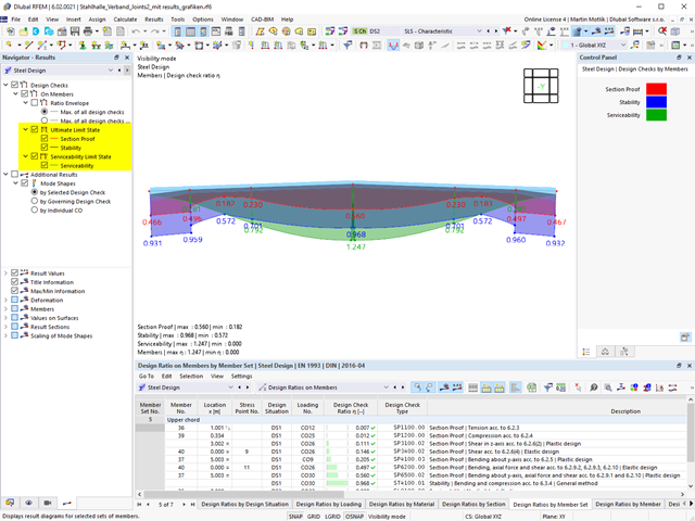
Jeśli projekt się powiedzie, nadejdzie czas. Ponieważ program wykonuje za Ciebie wiele procesów. Przeprowadzone kontrole obliczeń są na przykład wyświetlane w tabeli. Tutaj wyświetlane są wszystkie szczegóły wyników. Dzięki przejrzyście przedstawionym wzorom obliczeniowym wyniki są bezproblemowe i zrozumiałe. Nie ma tu efektu "czarnej skrzynki".
Obliczenia są przeprowadzane we wszystkich decydujących miejscach prętów i przedstawiane graficznie w postaci wykresu wyników. Ponadto w wynikach dostępne są szczegółowe grafiki, takie jak rozkład naprężeń w przekroju lub decydujący kształt postaci drgań.
Wszystkie dane wejściowe i wyniki są częścią protokołu wydruku programu RFEM/RSTAB. Zawartość protokołu i jego zakres można wybrać specjalnie dla poszczególnych warunków projektowych.
- 002375
- Ogólne informacje
- Projektowanie konstrukcji drewnianych RFEM 6
- Projektowanie konstrukcji drewnianych RSTAB 9
W przypadku obliczeń zgodnie z Eurokodem 5 parametry załączników krajowych (NA) są zintegrowane dla następujących krajów:
-
 DIN EN 1995-1-1/NA:2014-07 (Niemcy)
 -
 ÖNORM EN 1995-1-1/NA:2019-06 (Austria)
 -
 SN EN 1995-1-1/NA:2015-03 (Szwajcaria)
 -
 BDS EN 1995-1-1/NA:20157-06 (Bułgaria)
 -
 BS EN 1995-1-1/NA:2019-09 (Wielka Brytania)
 -
 CEN EN 1995-1-1/2014-05 (Unia Europejska)
 -
 CYS EN 1995-1-1/NA:2019-06 (Cypr)
 -
 CZE EN 1995-1-1/NA:2015-05 (Republika Czeska)
 -
 DS EN 1995-1-1/NA:2019-09 (Dania)
 -
 ELOT EN 1995-1-1/NA:2010-01 (Grecja)
 -
 EVS EN 1995-1-1/NA:2015-11 (Estonia)
 -
 HRN EN 1995-1-1/NA:2015-03 (Chorwacja)
 -
 I S. EN 1995-1-1/NA:2014-05 (Irlandia)
 -
 ILNAS EN 1995-1-1/NA:2020-3 (Luksemburg)
 -
 IST EN 1995-1-1/NA:2014-09 (Islandia)
 -
 LST EN 1995-1-1/NA:2014-06 (Litwa)
 -
 LVS EN 1995-1-1/NA:2014-12 (Łotwa)
 -
 MSZ EN 1995-1-1/NA:2015-06 (Węgry)
 -
 NBN EN 1995-1-1/NA:2014-06 (Belgia)
 -
 NEN EN 1995-1-1/NA:2014-06 (Holandia)
 -
 NF EN 1995-1-1/NA:2020-04 (Francja)
 -
 NP EN 1995-1-1/NA:2014-09 (Portugalia)
 -
 NS EN 1995-1-1/NA:2014-08 (Norwegia)
 -
 PN EN 1995-1-1/NA:2014-07 (Polska)
 -
 SFS EN 1995-1-1/NA:2016-12 (Finlandia)
 -
 SIST EN 1995-1-1/NA:2018-01 (Słowenia)
 -
 SR EN 1995-1-1/NA:2014-12 (Rumunia)
 -
 SS EN 1995-1-1/NA:2018-02 (Singapur)
 -
 SS EN 1995-1-1/NA:2014-05 (Szwecja)
 -
 STN EN 1995-1-1/NA:2019-12 (Słowacja)
 -
 TKP EN 1995-1-1/NA:2019-09 (Białoruś)
 -
 UNE EN 1995-1-1/NA:2016-04 (Hiszpania)
 -
 UNI EN 1995-1-1/NA:2016-11 (Włochy)
- 002379
- Ogólne informacje
- Projektowanie konstrukcji drewnianych RFEM 6
- Projektowanie konstrukcji drewnianych RSTAB 9
Dla podpór bocznych konstrukcji często nie są przeprowadzane obliczenia odporności ogniowej. Chcesz rozwiązać ten problem w swoim projekcie? Aby uwzględnić ten fakt w obliczeniach, można zdefiniować inne długości prętów zastępczych dla sytuacji pożarowej.