86 Wyniki
Wyświetl wyniki:
Sortuj według:

W rozszerzeniu Połączenia stalowe można używać nie tylko zwykłych typów prętów 'Belka', 'Kratownica' itd., ale także typu pręta 'Belka wynikowa' oraz przekroje z elementów powierzchniowych. Należy wybrać odpowiedni przekrój dla belki wynikowej, a następnie zdefiniować otwory prętowe w modelu powierzchniowym za pomocą edytora prętów.

W rozszerzeniu Połączenie stalowe można rozmieszczać obiekty w odniesieniu do innych obiektów.

Komponent 'Kontakt powierzchniowy' w rozszerzeniu Połączenia stalowe umożliwia uwzględnienie kontaktu ciśnieniowego między dwiema równoległymi płytami/płytami prętowymi. W takim przypadku można opcjonalnie uwzględnić tarcie między powierzchniami

Komponent "Stub" jest dostępny w rozszerzeniu Połączenia stalowe. Umożliwia ona wydłużenie pręta za pomocą połączenia płatwi z innym prętem (krótkiem) i połączenie go z komponentem odniesienia.

W rozszerzeniu Połączenia stalowe można teraz układać płyty w różne kształty geometryczne. Oprócz „Prostokąta” i „Okręgu” dostępny jest nowy kształt „Wielokąt”. Forma wielokąta jest określana przez zdefiniowaną współrzędną punktu.

Wynik obliczeń sejsmicznych jest podzielony na dwie sekcje: wymagania dotyczące prętów i połączeń.
"Wymagania sejsmiczne" zawierają Wymaganą wytrzymałość na zginanie i Wymaganą wytrzymałość na ścinanie połączenia belka-słup dla ram sprężystych. Są one wyszczególnione w zakładce 'Połączenia ram momentowych według prętów'. W przypadku ram stężonych w zakładce 'Połączenie stężone według pręta' podawana jest Wymagana wytrzymałość połączenia na rozciąganie oraz Wymagana wytrzymałość połączenia na ściskanie stężeń.
Przeprowadzone kontrole obliczeń są przedstawiane w tabelach. W szczegółach kontroli obliczeń w przejrzysty sposób przedstawione są wzory i odniesienia do normy.

W konfiguracji granicznej dla wymiarowania połączenia stalowego istnieje możliwość modyfikacji granicznego odkształcenia plastycznego dla spoin.

- 002304
- Ogólne informacje
- Projektowanie konstrukcji stalowych RFEM 6
- Projektowanie konstrukcji stalowych RSTAB 9
- W przypadku obliczeń zgodnie z Eurokodem 3 parametry załączników krajowych (NA) są zintegrowane dla następujących krajów:
-
 DIN EN 1993-1-1/NA:2016-04 (Niemcy)
 -
 ÖNORM EN 1993-1-1/NA:2015-12 (Austria)
 -
 SN EN 1993-1-1/NA:2016-07 (Szwajcaria)
 -
 BDS EN 1993-1-1/NA:2015-10 (Bułgaria)
 -
 BS EN 1993-1-1/NA:2016-07 (Wielka Brytania)
 -
 CEN EN 1993-1-1/2015-06 (Unia Europejska)
 -
 CYS EN 1993-1-1/NA:2015-07 (Cypr)
 -
 CZE EN 1993-1-1/NA:2016-06 (Republika Czeska)
 -
 DS EN 1993-1-1/NA:2015-07 (Dania)
 -
 ELOT EN 1993-1-1/NA:2017-01 (Grecja)
 -
 EVS EN 1993-1-1/NA:2015-08 (Estonia)
 -
 HRN EN 1993-1-1/NA:2016-03 (Chorwacja)
 -
 I S. EN 1993-1-1/NA:2016-03 (Irlandia)
 -
 ILNAS EN 1993-1-1/NA:2015-06 (Luksemburg)
 -
 IST EN 1993-1-1/NA:2015-11 (Islandia)
 -
 LST EN 1993-1-1/NA:2017-01 (Litwa)
 -
 LVS EN 1993-1-1/NA:2015-10 (Łotwa)
 -
 MS EN 1993-1-1/NA:2010-01 (Malezja)
 -
 MSZ EN 1993-1-1/NA:2015-11 (Węgry)
 -
 NBN EN 1993-1-1/NA:2015-07 (Belgia)
 -
 NEN EN 1993-1-1/NA:2016-12 (Holandia)
 -
 NF EN 1993-1-1/NA:2016-02 (Francja)
 -
 NP EN 1993-1-1/NA:2009-03 (Portugalia)
 -
 NS EN 1993-1-1/NA:2015-09 (Norwegia)
 -
 PN EN 1993-1-1/NA:2015-08 (Polska)
 -
 SFS EN 1993-1-1/NA:2015-08 (Finlandia)
 -
 SIST EN 1993-1-1/NA:2016-09 (Słowenia)
 -
 SR EN 1993-1-1/NA:2016-04 (Rumunia)
 -
 SS EN 1993-1-1/NA:2019-05 (Singapur)
 -
 SS EN 1993-1-1/NA:2015-06 (Szwecja)
 -
 STN EN 1993-1-1/NA:2015-10 (Słowacja)
 -
 TKP EN 1993-1-1/NA:2015-04 (Białoruś)
 -
 UNE EN 1993-1-1/NA:2016-02 (Hiszpania)
 -
 UNI EN 1993-1-1/NA:2015-08 (Włochy)
-
- W obliczeniach zgodnie z amerykańską normą AISC 360 uwzględniono następujące metody analizy:
-
 Obliczenia współczynnika obciążenia i odporności (LRFD)
 -
Projektowanie dopuszczalnych naprężeń (ASD)
-

Parametry załączników krajowych (NA) do Eurokodu 3 z następujących krajów są zintegrowane:
-
DIN EN 1993-1-1/NA:2016-04 (Niemcy)
-
ÖNORM EN 1993-1-1/NA:2015-12 (Austria)
-
SN EN 1993-1-1/NA:2016-07 (Szwajcaria)
-
BDS EN 1993-1-1/NA:2015-10 (Bułgaria)
-
BS EN 1993-1-1/NA:2016-07 (Wielka Brytania)
-
CEN EN 1993-1-1/2015-06 (Unia Europejska)
-
CYS EN 1993-1-1/NA:2015-07 (Cypr)
-
CSN EN 1993-1-1/NA:2016-06 (Republika Czeska)
-
DS EN 1993-1-1/NA:2015-07 (Dania)
-
ELOT EN 1993-1-1/NA:2017-01 (Grecja)
-
EVS EN 1993-1-1/NA:2015-08 (Estonia)
-
HRN EN 1993-1-1/NA:2016-03 (Chorwacja)
-
I S. EN 1993-1-1/NA:2016-03 (Irlandia)
-
ILNAS EN 1993-1-1/NA:2015-06 (Luksemburg)
-
IST EN 1993-1-1/NA:2015-11 (Islandia)
-
LST EN 1993-1-1/NA:2017-01 (Litwa)
-
LVS EN 1993-1-1/NA:2015-10 (Łotwa)
-
MS EN 1993-1-1/NA:2010-01 (Malezja)
-
MSZ EN 1993-1-1/NA:2015-11 (Węgry)
-
NBN EN 1993-1-1/NA:2015-07 (Belgia)
-
NEN EN 1993-1-1/NA:2016-12 (Holandia)
-
NF EN 1993-1-1/NA:2016-02 (Francja)
-
NP EN 1993-1-1/NA:2009-03 (Portugalia)
-
NS EN 1993-1-1/NA:2015-09 (Norwegia)
-
PN EN 1993-1-1/NA:2015-08 (Polska)
-
SFS EN 1993-1-1/NA:2015-08 (Finlandia)
-
SIST EN 1993-1-1/NA:2016-09 (Słowenia)
-
SR EN 1993-1-1/NA:2016-04 (Rumunia)
-
SS EN 1993-1-1/NA:2019-05 (Singapur)
-
SS EN 1993-1-1/NA:2015-06 (Szwecja)
-
STN EN 1993-1-1/NA:2015-10 (Słowacja)
-
TKP EN 1993-1-1/NA:2015-04 (Białoruś)
-
UNE EN 1993-1-1/NA:2016-02 (Hiszpania)
-
UNI EN 1993-1-1/NA:2015-08 (Włochy)

W rozszerzeniu Połączenia stalowe można zdefiniować kilka żeber jednocześnie na jednym pręcie lub płycie. Układ może być zdefiniowany według układu ortogonalnego lub biegunowego.
- 002320
- Ogólne informacje
- Projektowanie konstrukcji stalowych RFEM 6
- Projektowanie konstrukcji stalowych RSTAB 9
- Ręczne określenie temperatury krytycznej elementu lub automatyczne określenie temperatury elementu przez żądany czas
- Szeroki wybór krzywych pożaru: standardowa krzywa temperatura-czas, krzywa pożaru zewnętrznego, krzywa węglowodorów
- Ręczne dostosowywanie istotnych współczynników do określania temperatury stali
- Uwzględnienie cynkowania ogniowego elementów konstrukcyjnych przy określaniu temperatury stali
- Wyniki wykresu temperatura-czas dla temperatury gazu i stali
- Podczas określania temperatury można uwzględnić okładzinę ogniochronną w postaci obrysu lub okładziny skrzynkowej wykonanej z materiałów niezależnych od temperatury
- Wymiarowanie prętów ze stali węglowej lub nierdzewnej
- Obliczenia przekrojów i analiza stateczności (metoda prętów zastępczych) zgodnie z EN 1993-1-2, rozdz. 4.2.3
- Obliczenia przekrojów klasy 4 zgodnie z EN 1993-1-2, Załącznik E.

Za pomocą komponentu "Cięcie płyty" można ciąć blachy (np. blachy węzłowe, blachy środnika itp.). Dostępne są różne metody cięcia:
- Płaszczyzna: Cięcie jest wykonywane na powierzchni najbliższej płycie odniesienia.
- Powierzchnia: Wycinane są tylko przecinające się części płyt.
- Bryła ograniczająca: Najbardziej zewnętrzny wymiar, szerokość i wysokość, jest wycinany jako prostokąt.
- Otoczka wypukła: Zewnętrzna otoczka przekroju służy do przycinania płyty. Jeżeli w węzłach narożnych przekroju występują zaokrąglenia, cięcie jest do nich dostosowywane.
- 002317
- Ogólne informacje
- Projektowanie konstrukcji stalowych RFEM 6
- Projektowanie konstrukcji stalowych RSTAB 9
- Obliczanie ugięć i porównanie z normatywnymi lub ręcznie dostosowanymi wartościami granicznymi
- Uwzględnienie wygięcia wstępnego w analizie ugięcia
- W zależności od typu sytuacji obliczeniowej możliwe są różne wartości graniczne
- Ręczne dostosowywanie długości odniesienia i segmentacji według kierunku
- Obliczanie ugięć w odniesieniu do konstrukcji początkowej lub do konstrukcji odkształconej
- Dalsze szczegółowe obliczenia w zależności od wybranej normy obliczeniowej (np. ograniczenie oddychania środnika zgodnie z EN 1993-2)
- Graficzne wyświetlanie wyników zintegrowane z RFEM/RSTAB; na przykład stopień wykorzystania wartości granicznej, odkształcenie lub ugięcie
- Pełna integracja wyników z protokołem wydruku programu RFEM/RSTAB
_(1).png?mw=640&hash=415f7bbaf70e41679bb0106e1cf91eaa8c493ec9)
- Automatyczne generowanie modeli do analizy ES: rozszerzenie automatycznie tworzy w tle model elementów skończonych (ES) połączenia stalowego.
- Uwzględnienie wszystkich sił wewnętrznych: Obliczenia obejmują wszystkie siły wewnętrzne (N , Vy, Vz ,My, Mz, MT ) i nie są ograniczone do obciążeń płaskich.
- Automatyczne przenoszenie obciążeń: Wszystkie kombinacje obciążeń są automatycznie przenoszone do modelu analitycznego ES połączenia. Obciążenia są przenoszone bezpośrednio z programu RFEM, dzięki czemu ręczne wprowadzanie danych nie jest konieczne.
- Wydajne modelowanie: Rozszerzenie pozwala zaoszczędzić czas podczas modelowania złożonych sytuacji związanych z połączeniami. Utworzony model analityczny ES można również zapisać i wykorzystać do własnych szczegółowych analiz.
- Rozszerzalna biblioteka: Dostępna jest obszerna, rozszerzalna biblioteka zawierająca wstępnie zdefiniowane szablony połączeń stalowych.
- Szerokie zastosowanie: Rozszerzenie jest odpowiednie do tworzenia połączeń każdego typu i kształtu, jest kompatybilne z prawie wszystkimi przekrojami walcowanymi, spawanymi, złożonymi i cienkościennymi.

- 002132
- Wyniki
- Projektowanie konstrukcji stalowych RFEM 6
- Projektowanie konstrukcji stalowych RSTAB 9
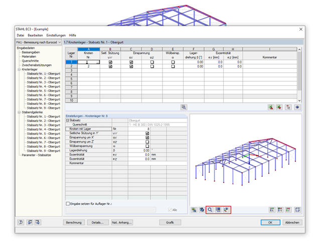
Układ konstrukcyjny należy wprowadzić i obliczyć siły wewnętrzne w programach RFEM i RSTAB. Użytkownik ma pełny dostęp do obszernych bibliotek materiałów i przekrojów. Masz pytania dotyczące programu? W programie RSECTION można również tworzyć przekroje ogólne.
Projektowanie konstrukcji stalowych jest w pełni zintegrowane z programami głównymi. Uwzględniają one automatycznie konstrukcję i dostępne wyniki obliczeń. Do wymiarowania konstrukcji aluminiowych można przydzielić dodatkowe dane, takie jak długości efektywne, redukcje przekroju lub parametry obliczeniowe. W wielu miejscach programu można łatwo wybrać elementy graficznie za pomocą funkcji [Wybierz].

- 002129
- Ogólne informacje
- Projektowanie konstrukcji stalowych RFEM 6
- Projektowanie konstrukcji stalowych RSTAB 9
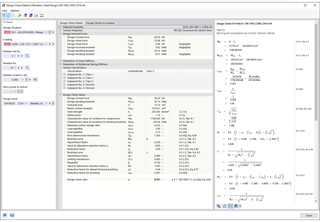
- Szeroki wybór dostępnych przekrojów, takich jak dwuteowniki walcowane; ceowniki; teowniki; kątowniki; profile zamknięte prostokątne i okrągłe; pręty okrągłe; przekroje symetryczne i niesymetryczne, parametryczne przekroje dwuteowe, teowe, kątowniki; przekroje złożone (przydatność do obliczeń zależy od wybranej normy)
- Wymiarowanie ogólnych przekrojów RSECTION (w zależności od formatów obliczeniowych dostępnych w odpowiedniej normie); na przykład obliczanie naprężeń zastępczych
- Wymiarowanie prętów o zbieżnym przekroju (metoda zależna od normy)
- Możliwe jest dostosowanie istotnych współczynników obliczeniowych i parametrów normowych
- Elastyczność dzięki szczegółowym opcjom ustawień dla podstawy i zakresu obliczeń
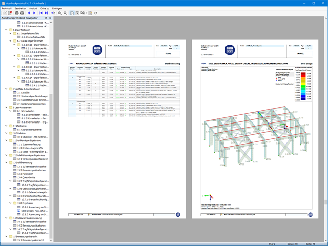
- Szybkie i przejrzyste wyświetlanie wyników dla globalnej oceny ich rozkładu na konstrukcji po zakończeniu obliczeń
- Szczegółowe wyniki obliczeń i niezbędne wzory (jasna i łatwa do zweryfikowania ścieżka wyników)
- Przejrzyste zestawienie wyników w formie numerycznej w stosownych oknach oraz możliwość ich graficznego przedstawienia na konstrukcji
- Integracja wyników z protokołem wydruku programu RFEM/RSTAB

- 002733
- Ogólne informacje
- Projektowanie konstrukcji stalowych RFEM 6
- Projektowanie konstrukcji stalowych RSTAB 9
Rozszerzenie Projektowanie konstrukcji stalowych umożliwia przeprowadzanie obliczeń sejsmicznych prętów stalowych zgodnie z AISC 341-16.
W tym celu dostępnych jest pięć typów systemów SFRS (Seismic Force-Resisting Systems).
- 002322
- Ogólne informacje
- Projektowanie konstrukcji stalowych RFEM 6
- Projektowanie konstrukcji stalowych RSTAB 9
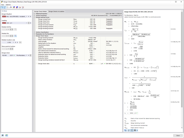
Weryfikacje wybranych prętów są przeprowadzane z uwzględnieniem decydującej temperatury elementu. W rozszerzeniu Projektowanie konstrukcji stalowych można przeprowadzić obliczenia przekrojów i analizy stateczności zgodnie z EN 1993-1-2, sekcja 4.2.3. Wszystkie niezbędne współczynniki i współczynniki redukcyjne są odpowiednio zapisywane i uwzględniane przy określaniu nośności.
Długości efektywne dla obliczeń pręta zastępczego są pobierane bezpośrednio z danych dotyczących wytrzymałości. Nie ma potrzeby'wprowadzania ich ponownie.
W każdym obliczeniu najpierw należy przeprowadzić klasyfikację przekroju. W przypadku przekrojów klasy 4 obliczenia są przeprowadzane automatycznie zgodnie z normą EN 1993-1-2, Załącznik E.
- 002328
- Ogólne informacje
- Projektowanie konstrukcji stalowych RFEM 6
- Projektowanie konstrukcji stalowych RSTAB 9
Czy przejrzysty układ jest dla Ciebie ważny? Program zapewnia przejrzysty przegląd wszystkich przeprowadzonych kontroli obliczeń dla danej normy obliczeniowej. Dla każdej kontroli obliczeń konieczne jest określenie kryterium obliczeniowego. Dostępne są również szczegóły obliczeń, w tym wartości początkowe, wyniki pośrednie i wyniki końcowe. W tym miejscu znajduje się również okno informacyjne, w którym szczegółowo przedstawiony jest przebieg obliczeń wraz z zastosowanymi wzorami, standardowymi źródłami i wynikami.

Teraz za pomocą kilku kliknięć można wstawiać blachy czołowe w połączeniach stalowych. Dane można wprowadzać za pomocą znanych typów definicji 'Offset' lub 'Wymiary i położenie'. Wprowadzając pręt odniesienia i płaszczyznę cięcia, można również pominąć część Przekrój pręta.
Za pomocą tego komponentu można łatwo modelować na przykład blachy czołowe na końcach słupa.

- 002330
- Ogólne informacje
- Projektowanie konstrukcji stalowych RFEM 6
- Projektowanie konstrukcji stalowych RSTAB 9
W zależności od kierunku można indywidualnie zdefiniować wszystkie długości odniesienia, które muszą zostać uwzględnione podczas obliczeń wartości granicznej ugięcia, a także które segmenty mają zostać sprawdzone. W tym celu należy zdefiniować podpory obliczeniowe w węzłach pośrednich pręta i przydzielić je do odpowiedniego kierunku na potrzeby analizy odkształceń. W ten sposób tworzone są segmenty, w których można zdefiniować wygięcie wstępne dla każdego kierunku i segmentu.
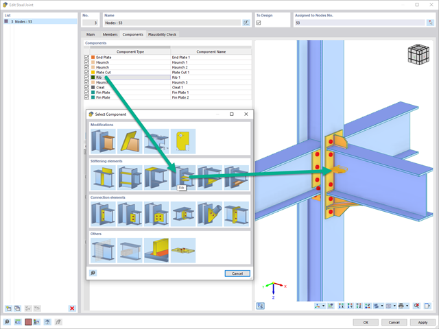
Za pomocą elementu "Żebro" można zdefiniować dowolną liczbę żeber podłużnych na blasze pręta. Wskazując obiekt odniesienia, można automatycznie określić na nim spoiny.
Komponent typu „żebro” może być również umieszczony na okrągłych profilach zamkniętych. Dafür wird zusätzlich die Vorgabe der Winkel zwischen den Rippen benötigt.
- 002329
- Ogólne informacje
- Projektowanie konstrukcji stalowych RFEM 6
- Projektowanie konstrukcji stalowych RSTAB 9
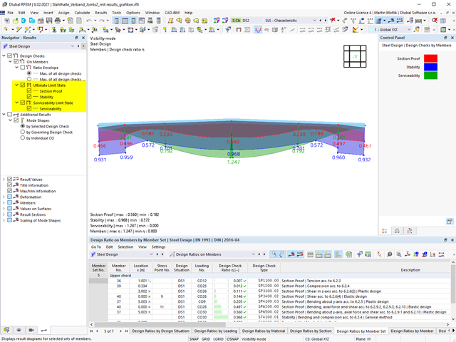
Wyniki obliczeń można znaleźć bezpośrednio w rozszerzeniu Projektowanie konstrukcji stalowych. Są one tam dostępne w formie tabelarycznej. Rozkład stopni wykorzystania można również wyświetlić graficznie. Zarówno w tabeli, jak i w postaci graficznej dostępne są liczne opcje filtrowania. Dzięki temu można wyświetlać żądane warunki projektowe według stanu granicznego lub typu obliczeń.

W Centrum Dlubal dostępna jest obszerna biblioteka połączeń dla rozszerzenia Połączenia stalowe.
Dostęp do tej biblioteki można uzyskać bezpośrednio z rozszerzenia i przydzielić wstępnie zdefiniowane połączenia do odpowiednich węzłów. Połączenia zdefiniowane przez użytkownika można również zapisywać w bibliotece w Centrum Dlubal.
- 002323
- Ogólne informacje
- Projektowanie konstrukcji stalowych RFEM 6
- Projektowanie konstrukcji stalowych RSTAB 9
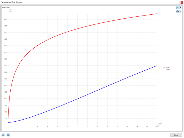
Po zakończeniu obliczeń, Dlubal Software przedstawia w przejrzysty sposób analizę odporności ogniowej wraz ze wszystkimi szczegółami wyników. Dzięki temu wyniki są zrozumiałe. Ponadto wyniki zawierają również wszystkie parametry wymagane do określenia temperatury elementu w czasie projektowania.
Rozkład temperatury w elemencie konstrukcyjnym można również ocenić za pomocą wykresu temperatura-czas.
Wszystkie tabele i grafiki wyników, w tym wyniki obliczeń stanu granicznego nośności i użytkowalności, można zintegrować z globalnym protokołem wydruku programu RFEM/RSTAB jako część wyników obliczeń konstrukcji stalowej.

Wyniki naprężeń i odkształceń według powierzchni można wyświetlić w tabeli wyników powierzchni zgodnie z grubością warstwy.
- 002324
- Ogólne informacje
- Projektowanie konstrukcji stalowych RFEM 6
- Projektowanie konstrukcji stalowych RSTAB 9
W przypadku obliczeń zgodnie z Eurokodem 3 parametry załączników krajowych (NA) są zintegrowane dla następujących krajów:
-
DIN EN 1993-1-1/NA:2020-11 (Niemcy)
-
ÖNORM EN 1993-1-1/NA:2015-12 (Austria)
-
SN EN 1993-1-1/NA:2016-07 (Szwajcaria)
-
BDS EN 1993-1-1/NA:2015-10 (Bułgaria)
-
BS EN 1993-1-1/NA:2016-07 (Wielka Brytania)
-
CEN EN 1993-1-1/2015-06 (Unia Europejska)
-
CYS EN 1993-1-1/NA:2015-07 (Cypr)
-
CZE EN 1993-1-1/NA:2016-06 (Republika Czeska)
-
DS EN 1993-1-1/NA:2015-07 (Dania)
-
ELOT EN 1993-1-1/NA:2017-01 (Grecja)
-
EVS EN 1993-1-1/NA:2015-08 (Estonia)
-
HRN EN 1993-1-1/NA:2016-03 (Chorwacja)
-
I S. EN 1993-1-1/NA:2016-03 (Irlandia)
-
ILNAS EN 1993-1-1/NA:2015-06 (Luksemburg)
-
IST EN 1993-1-1/NA:2015-11 (Islandia)
-
LST EN 1993-1-1/NA:2017-01 (Litwa)
-
LVS EN 1993-1-1/NA:2015-10 (Łotwa)
-
MS EN 1993-1-1/NA:2010-01 (Malezja)
-
MSZ EN 1993-1-1/NA:2015-11 (Węgry)
-
NBN EN 1993-1-1/NA:2015-07 (Belgia)
-
NEN EN 1993-1-1/NA:2016-12 (Holandia)
-
NF EN 1993-1-1/NA:2016-02 (Francja)
-
NP EN 1993-1-1/NA:2009-03 (Portugalia)
-
NS EN 1993-1-1/NA:2015-09 (Norwegia)
-
PN EN 1993-1-1/NA:2015-08 (Polska)
-
SFS EN 1993-1-1/NA:2015-08 (Finlandia)
-
SIST EN 1993-1-1/NA:2016-09 (Słowenia)
-
SR EN 1993-1-1/NA:2016-04 (Rumunia)
-
SS EN 1993-1-1/NA:2019-05 (Singapur)
-
SS EN 1993-1-1/NA:2015-06 (Szwecja)
-
STN EN 1993-1-1/NA:2015-10 (Słowacja)
-
TKP EN 1993-1-1/NA:2015-04 (Białoruś)
-
UNE EN 1993-1-1/NA:2016-02 (Hiszpania)
-
UNI EN 1993-1-1/NA:2015-08 (Włochy)
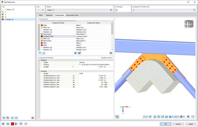
W rozszerzeniu Połączenie stalowe można użyć elementu "Bryła pomocnicza", aby dokładnie ciąć płyty i inne elementy konstrukcyjne. W ramach tego elementu, rolę obiektu pomocniczego mogą pełnić kształty takie jak sześcian, walec lub dowolny przekrój.
Przejdź do filmu
Proces znajdowania kształtu tworzy model konstrukcyjny z aktywnymi siłami w "przypadku obciążenia sprężonego" Ten przypadek obciążenia pokazuje przemieszczenie od początkowego położenia wejściowego do ustalonej geometrii w wynikach deformacji. W wynikach opartych na sile lub naprężeniach (siły wewnętrzne prętów i powierzchni, naprężenia w bryłach, ciśnienia gazu itp.) określany jest stan w celu zachowania znalezionej formy. Do analizy kształtu geometrycznego program oferuje dwuwymiarowy wykres konturowy z przedstawieniem wysokości bezwzględnej i wykresem nachylenia do wizualizacji sytuacji na zboczu.
Teraz przeprowadzane są dalsze obliczenia i analiza statyczno-wytrzymałościowa całego modelu. W tym celu program przenosi geometrię zorientowaną na kształt wraz z odkształceniami zależnymi od elementów do uniwersalnego stanu początkowego. Można go teraz używać w przypadkach obciążeń i kombinacjach obciążeń.

- Wybór węzłów w modelu RFEM, automatyczne rozpoznawanie i przydzielanie prętów połączonych z wybranym węzłem
- Dostępnych jest wiele wstępnie zdefiniowanych elementów ułatwiających wprowadzanie typowych komponentów połączeń (np. blachy czołowe, żebra usztywniające)
- Uniwersalne komponenty bazowe (płyty, spoiny, płaszczyzny pomocnicze) do odwzorowania złożonych geometrii połączeń
- Użytkownik nie musi ręcznie edytować modelu MES połączenia, podstawowe ustawienia obliczeń można zmienić w oknie konfiguracji połączenia
- Automatyczne dostosowywanie geometrii połączenia, nawet w przypadku późniejszej edycji prętów, z uwagi na parametryczną definicję położenia komponentów względem siebie
- Równolegle do wprowadzania danych program przeprowadza kontrolę poprawności, aby szybko wykryć brakujące dane wejściowe lub kolizje elementów.
- Wizualizacja geometrii połączenia, która jest aktualizowana równolegle z wprowadzaniem danych