


Description
The model is based on the example 4 of [1]: Point-supported slab.
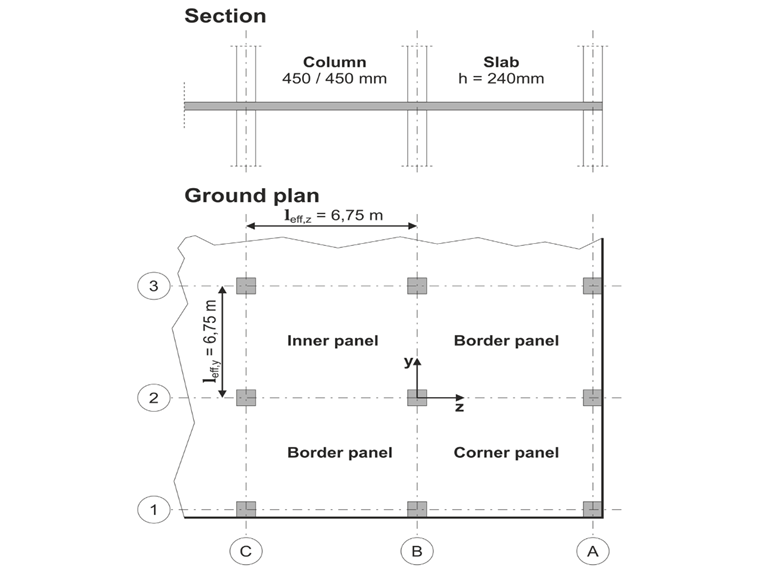
The flat slab of an office building with crack-sensitive lightweight walls is to be designed. Inner, border and corner panels are to be investigated. The columns and the flat slab are monolithically joined. The edge and corner columns are placed flush with the edge of the slab. The axes of the columns form a square grid. It is a rigid system (building braced with wall plates).
The office building has 5 floors with a floor height of 3.0 m. The environmental conditions to be assumed are defined as "closed interior spaces". There are predominantly static actions.
The focus of this example is to determine the slab moments and the required reinforcement above the columns under full load.
| Material | Concrete C35/45 | Modulus of Elasticity | E | 34000 | N/mm2 |
| Design value of concrete compressive strength | fcd | 19.8 | N/mm2 | ||
| Reinforcing Steel B500S(B) | Characteristic yield strength | fyk | 500.000 | N/mm2 | |
| Design yield strength | fyd | 435.000 | N/mm2 | ||
| Geometry | Flat slab | Slab thickness | h | 240 | mm |
| Span of a panel in y-direction | leff,y | 6.750 | m | ||
| Span of a panel in z-direction | leff,z | 6.750 | m | ||
| Column cross-section | Width | b | 450 | mm | |
| Height | h | 450 | mm | ||
| Load | Permanant loads | Reinforced concrete slab | 6.000 | kN/m2 | |
| Covering and suspended ceiling | 1.250 | kN/m2 | |||
| Total characteristic value | gk | 7.250 | kN/m2 | ||
| Total design value | gd | 9.790 | kN/m2 | ||
| Variable loads | Live load | 2.000 | kN/m2 | ||
| Partitions aggregate | 2.000 | kN/m2 | |||
| Total characteristic value | qk,1 | 3.25 | kN/m2 | ||
| Total design value | qd | 4.880 | kN/m2 |
The approximation method used in [1] is not suitable as a reference solution for the FE calculation. As an alternative, the reference solution is established as a range of solutions derived from various FE calculations, as documented in the EvaDAT website. The acceptable range of results is limited to a +/- 10% deviation from the median of the available results.
RFEM Settings
- The columns are modeled as nodal supports with a vertical spring constant Cu,Z of 2295000 kN/m and a torsion spring constant CΦ of 232368 kNm/rad in x- und y-direction.
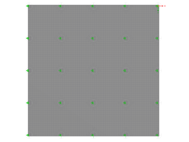
- The target length of the finite elements lFE is 0.450 m.
- In addition, a FE mesh refinement is applied to each nodal support. The mesh refinement type is circular with a radius R=0.700 m, an inner target FE length LFE,i=0.100 m and an outter target FE length LFE,o=0.300 m.
- The evaluation of the moments takes place on the column periphery
- The first reinforcement layer is assumed to have a concrete cover of d1 = 3.0 cm and a bar diameter of 20 mm. This results in an effective depth dx = 200 mm and dy = 180 mm.
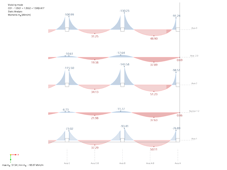
- Slab Moment in x-direction
moment [kNm/m] in x-direction Axis Result location RFEM Result Reference solution Median +/- 10% range Axis 1 Column C -73.0 -74.4 -67.0 -81.8 Column B -93.4 -95.7 -86.1 -105.2 Column A -76.9 -78.1 -70.2 -85.9 Span C-B 37.3 37.5 33.8 41.3 Span B-A 49.7 50.5 45.4 55.5 Axis 2 Column C -115.5 -115.8 -104.2 -127.4 Column B -143.6 -144.7 -130.2 -159.2 Column A -98.5 -99.2 -89.2 -109.1 Span C-B 34.1 34.6 31.1 38.1 Span B-A 51.2 52.1 46.8 57.3 Axis 3 Column C -101.0 -100.7 -90.6 -110.7 Column B -130.2 -130.8 -117.7 -143.9 Column A -91.2 -91.8 -82.6 -100.9 Span C-B 31.3 31.6 28.4 34.7 Span B-A 48.9 49.7 44.7 54.6 Axis 1-2 Column C -6.7 -7.0 -6.3 -7.7 Column B -11.8 -11.9 -10.7 -13.1 Span C-B 22.0 22.0 19.8 24.2 Span B-A 37.6 37.7 33.9 41.4 Axis 2-3 Column C -10.7 -11.1 -9.9 -12.2 Column B -17.6 -17.9 -16.1 -19.7 Span C-B 19.4 19.5 17.5 21.4 Span B-A 37.9 37.9 34.1 41.7
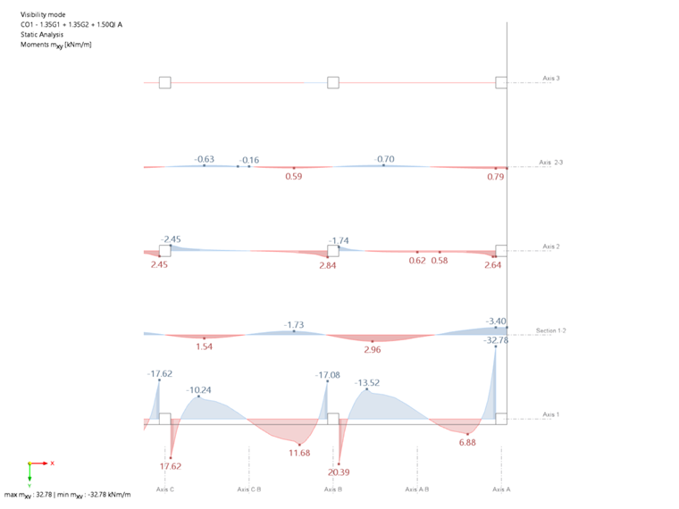
- Trosional Moment Trosional moment m_xy
Trosional moment m_xy [kNm/m] Axis Result location RFEM Result Reference solution Average result +/- 10% range Axis 1 Column C 17.62 16.7 15.0 18.3 Column B 20.4 19.1 17.1 21.0 Column A 32.8 31.1 28.0 34.2 Axis 2 Column C 2.45 2.4 2.1 2.6 Column B 1.74 1.7 1.5 1.9 Column A 2.64 2.7 2.4 3.0
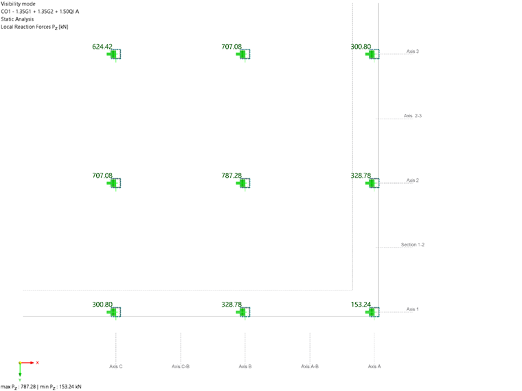
- Support Forces
Support Forces [kN] Column RFEM result Reference solution Median +/- 5% range C1=A3 300.8 300.9 285.9 316.0 B1=A2 328.8 328.8 312.3 345.2 A1 153.2 153.4 145.7 161.0 C2=B3 707.1 707.0 671.7 742.4 B2 787.3 787.0 747.7 826.4 C3 624.4 624.5 593.3 655.7
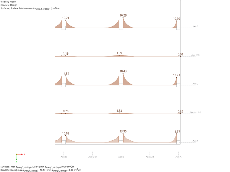
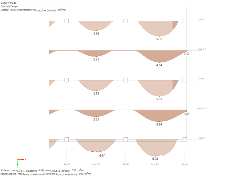
- Required Reinforcement
Required Reinforcement asx [cm2/m] in x-direction, dx = 200 mm Axis Result location RFEM results Reference solution Median +/- 10% range Axis 1 Column C 10.82 10.8 9.7 11.9 Column B 13.95 13.8 12.4 15.2 Column A 13.37 13.0 11.7 14.3 Span C-B 4.51 4.5 4.1 5.0 Span B-A 6.08 6.1 5.5 6.7 Axis 2 Column C 14.5 16.1 14.4 17.7 Column B 18.43 20.3 18.3 22.3 Column A 12.2 12.5 11.3 13.8 Span C-B 3.89 3.9 3.5 4.3 Span B-A 5.91 5.9 5.3 6.5 Axis 3 Column C 12.21 13.5 12.1 14.8 Column B 16.29 17.8 16.0 19.5 Column A 10.9 11.1 10.0 12.2 Span C-B 3.56 3.6 3.2 3.9 Span B-A 5.62 5.7 5.1 6.2 Axis 1-2 Column C 0.8 0.8 0.7 0.9 Column B 1.33 1.3 1.2 1.5 Span C-B 2.53 2.5 2.2 2.7 Span B-A 4.34 4.3 3.9 4.8 Axis 2-3 Column C 1.19 1.2 1.1 1.3 Column B 1.99 2.0 1.8 2.2 Span C-B 2.2 2.2 1.9 2.4 Span B-A 4.34 4.3 3.9 4.8
Required Reinforcement asy [cm2/m] in y-direction, dx = 180 mm Axis Result location RFEM results Reference solution Median +/- 10% range Axis A Column 3 12.34 12.3 11.0 13.5 Column 2 15.98 15.7 14.2 17.3 Column 1 15.31 14.8 13.4 16.3 Span 2-3 5.04 5.0 4.5 5.5 Span 1-2 6.81 6.8 6.2 7.5 Axis B Column 3 16.64 17.9 16.1 19.6 Column 2 21.31 22.7 20.4 24.9 Column 1 13.93 13.9 12.5 15.2 Span 2-3 4.34 4.4 3.9 4.8 Span 1-2 6.6 6.7 6.0 7.3 Axis C Column 3 13.93 15.0 13.5 16.4 Column 2 18.67 19.7 17.7 21.7 Column 1 12.42 12.3 11.1 13.5 Span 2-3 3.97 4.0 3.6 4.4 Span 1-2 6.29 6.4 5.7 7.0 Axis A-B Column 3 0.85 0.9 0.8 1.0 Column 2 1.47 1.5 1.3 1.6 Span 2-3 2.82 2.8 2.5 3.0 Span 1-2 4.85 4.8 4.4 5.3 Axis B-C Column 3 1.34 1.4 1.2 1.5 Column 2 2.22 2.2 2.0 2.4 Span 2-3 2.46 2.4 2.2 2.7 Span 1-2 4.83 4.8 4.4 5.3
Results
In the following tables, the results of RFEM 6 are compared with the reference solution.
The internal forces and the required reinforcement calculated by RFEM 6 are consistently within the defined result range of +/- 10% of the median value.