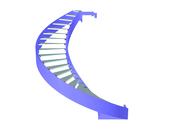
Spiral Staircase with Glass Steps, Zlín, Czech Republic
Customer Project
The goal was to design a spiral staircase with glass steps and railings spanning over 2 floors. With sophisticated anchoring details and helical stringers created from subtle rectangular hollow section, a light and elegant staircase was formed. The interior spiral staircase is located inside of the educational, training and rehabilitation center in the city of Zlín.
Structural Analysis |
Ing. Vítězslav Hapl Ing. Jan Mařík, Ph.D.
Ing. Jan Seifert KONSTAT s.r.o. |
Architectural Design | CUBE DESIGN s.r.o. |
Construction | STAIRS design s.r.o. |
Model Parameters
Model
Structure
Looking from the structural point of view and excluding the rigidity of the reinforced concrete structure, the staircase can be separated into two parts –the 1st to 2nd floor portion and the 2nd to 3rd floor portion. The staircase supporting structure consists of internal and external helical stringers. The stringers are fixed to the landings (welded to the pre-built anchor elements) and to the 1st floor slab (anchored via Hilti adhesive anchors).
The stringers are made of welded closed hollow sections with recessed flanges. The upper flange recess creates a groove for mounting a glass railing, while the lower flange recess is purely an architectural element. The stair treads are made of laminated tempered glass.
The treads are attached to a cantilevered box section (1 inch wide x 1 inch deep) further welded to the stringer web at four locations. The glass tread is supported on the cantilevers by an elastic band and fastened with metric screws. Due to the rigidity of the step-stringer connection, the steps are considered in the computational model.
The inner and outer stringer railings are made of laminated tempered glass bent to the appropriate radius. The railing is inserted into the stringer groove, positioned by elastic spacers, and finally glued into the groove by a suitable elastic material. The railing is considered only as a load and therefore has no load-bearing function.
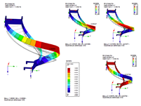
Model
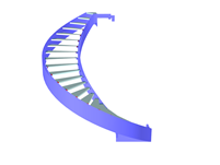
Due to the above-mentioned staircase floor independence, only one part of the staircase is modeled. The stringers and anchor elements are modeled with plate elements, and the stair treads are modeled as members. To estimate the maximum glass step loading and to evaluate the steel stringer maximum loading, two different stiffness values were used for the glass step connection and the support cantilever. The restraint in the reinforced concrete slab is modeled with a nonlinear failure under tension, elastic support applied to the anchor element’s individual surfaces.Project Location
Mladcová, ZlínKeywords
Steel stringers Glass steps RFEM
Write Comment...
Write Comment...
Contact us
Do you have questions or need advice?
Contact our free e-mail, chat, or forum support or find various suggested solutions and useful tips on our FAQ page.
Recommended Events
Videos
Models to Download
Knowledge Base Articles

New
Design of a welded truss
This technical article deals with the component and cross-section designs of a welded truss in the ultimate limit state. Furthermore, the deformation analysis in the serviceability limit state is described.
Screenshots
Product Features Articles

Material Database with Steels According to the Australian Standard AS/NZS 4600:2005
The material database in RFEM, RSTAB and SHAPE-THIN contains steels according to the Australian standard AS/NZS 4600:2005.Frequently Asked Questions (FAQ)
- In the RF‑/STEEL EC3 add-on module, I obtain an extremely high design ratio for a member in the case of "Biaxial bending, shear and axial force." Although the axial force is relatively high, the design ratio seems to be unrealistic. What is the reason?
- For which programs is the STEEL Warping Torsion add-on module available?
- I have just noticed that the STEEL EC3 add-on module also calculates with γM0 = 1.0 when designing a tension member, although it should actually be γM2 = 1.25. How can I perform the design correctly?
- Is it possible to design intermittent welds in the CRANEWAY add-on module?
- I design a cross-section created in the SHAPE‑THIN program by using the RF‑STEEL EC3 add-on module, but the program shows the error message "ER006 Invalid type of c/t-part for cross-section of type General." What can I do?
- For a buckling analysis, FE‑BUCKLING determines the governing shear stress of τ = 7.45 kN/cm², while RF‑/STEEL gives the result of the maximum shear stress of τ = 8.20 kN/cm². Where does this difference come from?
- Why do I get a design ratio for the stability analysis according to 6.2.9.1 in the STEEL EC3 add-on module? Why is a * added to Equation (6.36)?
- I design a frame with a taper (docked cross-section). STEEL EC3 classifies the taper in Cross-Section Class 3. Accordingly, the elastic resistances are taken into account, which is very unfavorable. According to the standard, the taper should be categorized in Class 1, and thus the plastic reserve should also be usable.
- When modeling a beam connection to a continuous column, I have the problem that the column flange fails under bending. If I add backing plates in the FRAME‑JOINT Pro add-on module, nothing changes for all design ratios. Why?