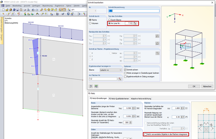
If the section was defined on an unused line, activate the "Integrate unutilized objects into surfaces" check box in FE Mesh Settings.
There is a section defined on Line 7 and Line 12 in Image 01. Line 7 has no other function for Surface 1. It is not the boundary line of Surface 1, nor does it have a support or a load. In FE Mesh Settings, the "Integrate unutilized objects into surfaces" check box is deactivated so that no result diagrams are displayed on Line 7. On the other hand, Line 12 is subjected to a load, so the result diagrams are displayed on this line. When selecting the "Integrate unutilized objects into surfaces" checkbox, the result diagrams are also displayed on Line 7.
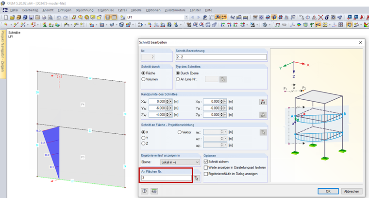
If the section runs through several surfaces, the respective surfaces have to be specified in the "On Surface No." section. Image 02 shows a section through Surface 3 and Surface 4. In the "On Surfaces No." section, only Surface No. 3 is specified, so that result diagrams are also only displayed on this surface. Surface 4 would have to be specified in the "On Surfaces No." section in order to display the result diagrams here as well.