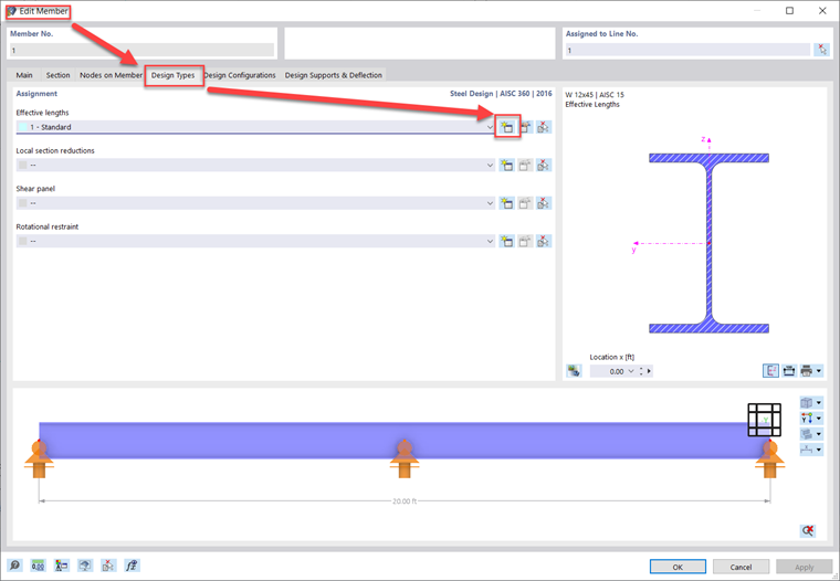
There are two options when it comes to defining effective lengths in RFEM 6. First, edit the member and navigate to the "Design Types" Tab. Second, create a new effective lengths definition.
Third, set whether you would like to calculate the critical moment according to the Eigenvalue method or Chapter F from the AISC. Fourth, navigate to the "Nodal Supports and Effective Lengths" tab. Within this tab there are two different methods that can be used.
Method 1: Nodal Supports
Referencing Member No. 1 in the attached model, for this column you can see a how the effective lengths for the Start, End, and Intermediate nodes are defined. First, click on Select Member or Member Set and then select the member. This will activate the intermediate nodes along the member length in the table. Next, check whether the node can move in the y/z axis (weak/strong axis), rotate about its local x-axis (torsion), and about its local z-axis (LTB).
The Warping (ω) input options will adjust the effective length for LTB, similar to the rotational z-axis restraint. For Ch. F calculations, the warping can be fully restrained or released. For Eigenvalue calculations, in addition to the fully restrained or released option, there is also the ability to set partial fixity with a warping spring constant.
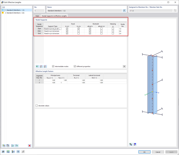
Top and bottom flanges can also be restrained separately by fixing the y-axis and releasing (unchecking) the rotation about the local x-axis restraint (torsion) for one of the member ends.

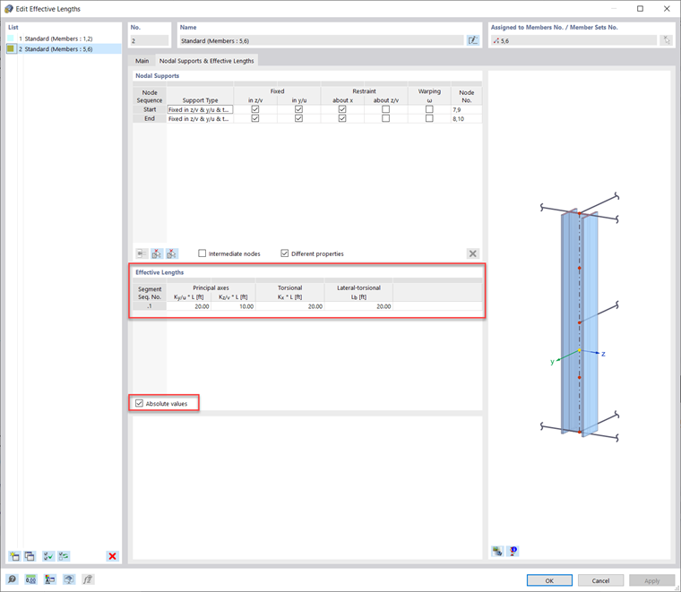
Method 2: "K" Factors and Absolute Values
Referencing Member No. 5 in the attached model, the effective length factors can be used to define the unbraced length directly and/or apply the appropriate member end conditions. To adjust the unbraced lengths directly instead of utilizing the nodes on the member (Method 1), the "K" factors can be entered manually in the table below. Or the "Absolute Values" can be entered by selecting the option "Absolute Values". Then the unbraced length itself can be entered manually instead. This method is best used when there are no intermediate nodes currently present on the member.