Adjusting the Length of Guidelines
Tips & Tricks
To open the dialog box for setting the grid, select Tools → Work Plane, Grid/Snap, Object Snap, Guidelines, or the corresponding button in the toolbar.
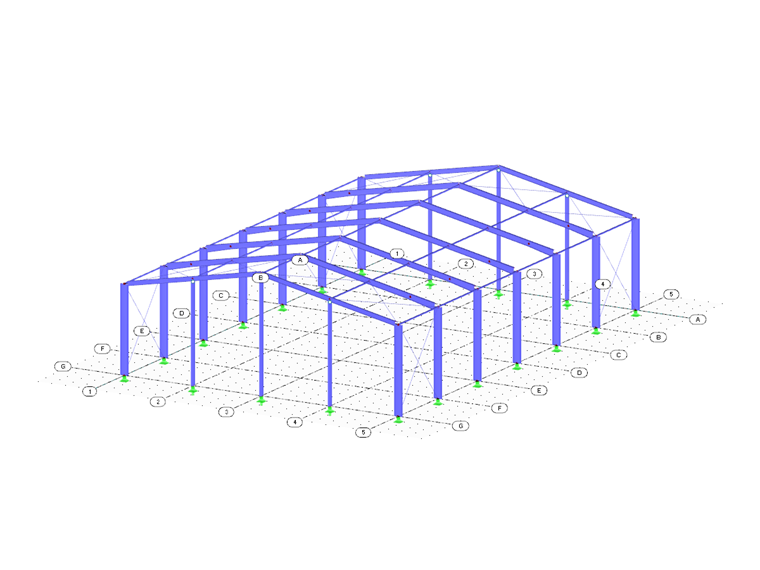
In the "Work Plane and Grid/Snap" dialog box, you can define the size of the grid using the number and spacing of grid points (Figure 1).
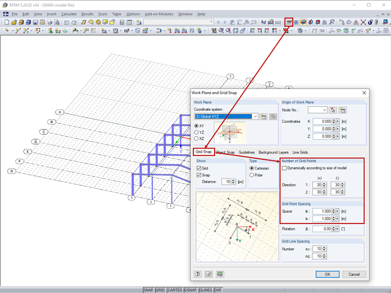
The orientation of the grid refers to the specified work plane zero point (Figure 2) as well as the defined rotation.
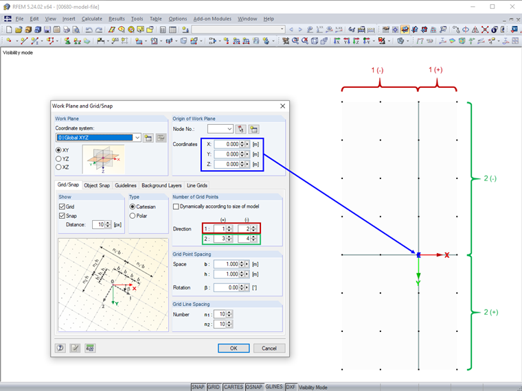
If the "Adjust grid of model size" option is active (Figure 3), the grid is automatically adjusted to the dimensions of the model.
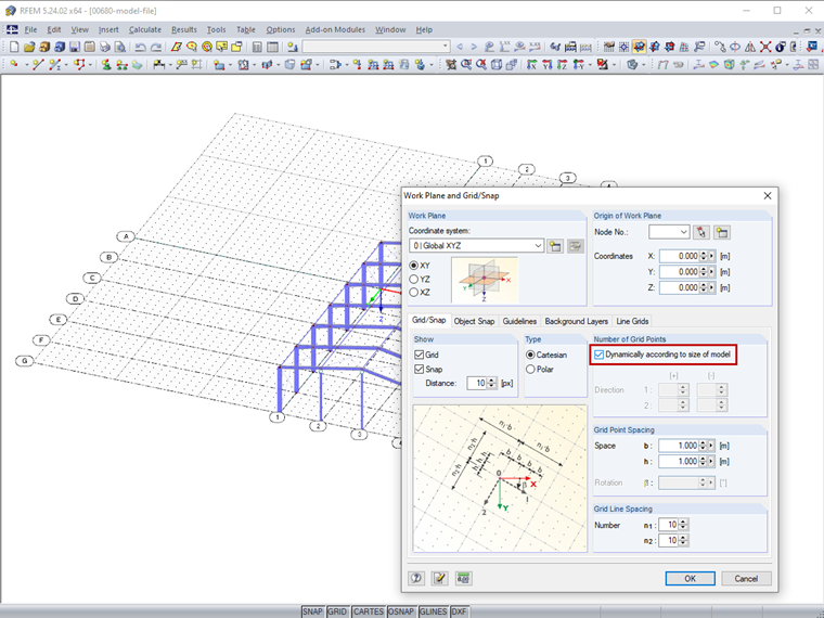
After confirming the grid settings with "OK", the guidelines are adjusted to the grid (Figure 4).
Author

Sonja von Bloh, M.Sc.
Product Engineering & Customer Support
Ms. von Bloh provides technical support for our customer and is responsible for the development of the SHAPE‑THIN program.
Keywords
Guideline Guideline length Grid Guide object
Links
- Useful Tools for Fast Generation of Structures in RFEM
- Useful Tools for Fast Generation of Structures in RSTAB
Write Comment...
Write Comment...
Contact us
Do you have questions or need advice?
Contact our free e-mail, chat, or forum support or find various suggested solutions and useful tips on our FAQ page.

New
You can assign comments to each element in RFEM and RSTAB (structure element, load element etc.).

New
Structural Analysis Models for Download
Download numerous structural models (for example, RFEM, RSTAB, or RWIND files) to utilize them for training purposes or for your projects.
- Is it possible to keep the results from RWIND Simulation when deleting the FE mesh if I only adjust materials or support conditions?
- How can I change the colors of the selection and preselection?
- Is it possible to make the generated member loads from area loads via plane to act eccentrically on the member cross-section?
- After the calculation in the RF‑/DYNAM Pro - Equivalent Loads add-on module, the size of my file has increased significantly. The performance has worsened enormously. What could be the reason for this?
- Why are my imperfections displayed graphically in different ways and can I adjust the display?
- What happens with the programs and add-on modules in the case of the timeout of a network license? And how can I increase the timeout?
- Why is it not possible to select a load case for design in the RF‑/STEEL add-on module, although it is defined in RFEM/RSTAB?
- Does the load generation also work for curved members?
- What effects can renumbering elements have on the printout report and the add -on modules?
- In my model, some surfaces are displayed in gray, while others are displayed in white without a gray filling. The "solid transparent" display type is selected for the graphics. How can all surfaces be displayed in gray?
Associated Products