Input
After selecting the "Result Beam" member type, it is necessary to set further parameters. There are four options available for specifying the integration area:
- Within a cuboid – quadratic: A quadratic integration area is used, the centroid of which is located in the member axis.
- Within a cuboid – general: A rectangular integration area is used, of which the centroid may vary.
- Within a cylinder: A circular integration area is used, of which the centroid is located in the member axis.
- From listed including objects: Only those elements for evaluation are used that are in the list of "Including Objects" and are within the possible effective area (see below).
If the integration area overlaps the objects that should not be taken into account, these objects can be defined in the "Except from Including Objects" list.
Effective Area of Result Beam
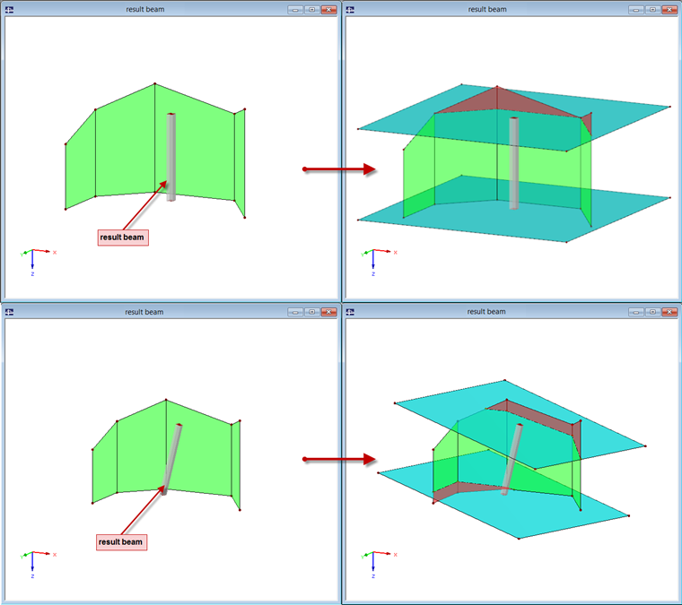
A result beam can only provide results of the elements located within a rectangular axis of the member start and end. All the elements outside these boundaries are not taken into account.
This is illustrated in Image 01: The results do not apply to the areas marked in red. The turquoise areas were manually modeled as auxiliary areas and represent the boundaries of the result beam.
Cross-Section
For the internal forces of the member, it is irrelevant which cross-section is used. So if you want to apply the result beam to only determine the internal forces, you can use any cross-section. However, if you want to perform further design in the add-on modules such as RF-STEEL EC3 or RF-CONCRETE Members, the cross-section plays an important role and thus should be defined precisely.
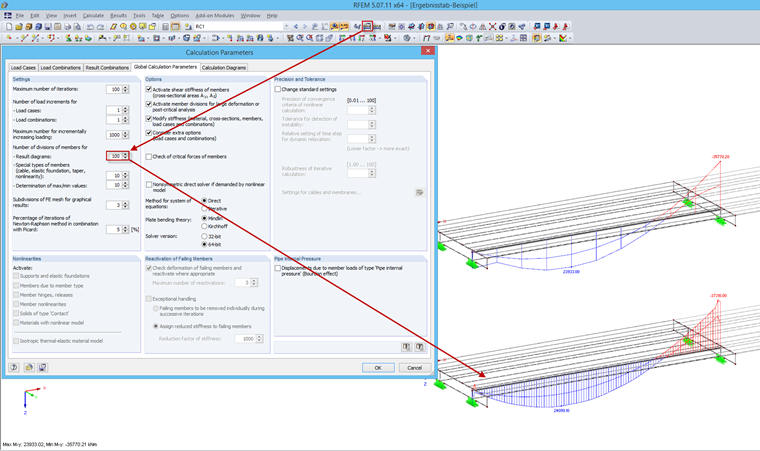
Member Division of Results
Since the distribution of internal forces is not very reliable, it is necessary to set a higher number of member divisions for result diagrams in the global calculation parameters.
Result Beam Position
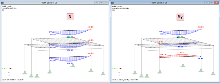
For the internal forces N, Vy, and Vz, the parallel distance of the result beam to the centroid of the including objects does not matter. So if you want to evaluate only the axial and shear forces, you can model the result member on or above the structure to get a clear display.
However, it is crucial for the internal forces Mt, My, and Mz to place the result beam in the centroid of the including objects. In addition to including moments, the axial forces multiplied by the distance of each FE mesh points are added to the centroid of the result beam.