


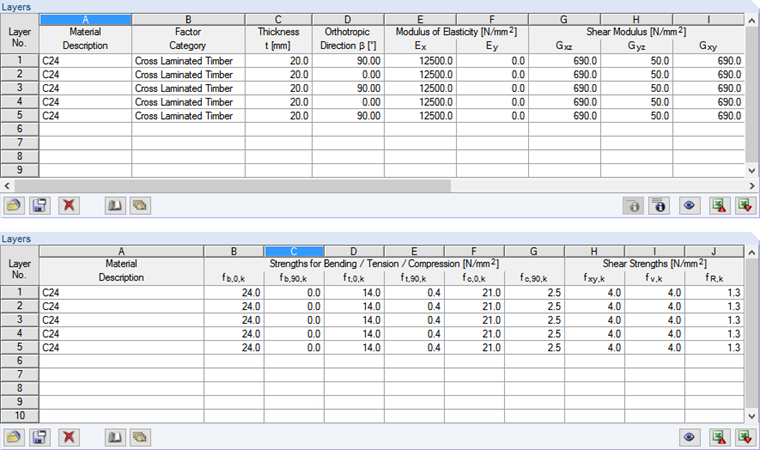
The determination of the slenderness ratio requires the effective moment of inertia I, among others. This can be calculated from the bending stiffness (y-direction) of the surface (see Image&bsp;03 in Part 1). Furthermore, the net area Anet is calculated, for which the components of the longitudinal layers in the y-direction are taken into account (see Image 02). Since the lower quantile value of the critical buckling stress is to be determined, the 5% quantile is to be used for the modulus of elasticity. For softwood timber, this should be 2/3 of the mean value of the elastic modulus, according to EN 338. The imperfection factor βc takes into account the precamber amplitude depending on the material. This factor is to be considered at 0.2 (L/300) for solid timber, and 0.1 (L/500) for glued-laminated timber and laminated veneer lumber. Further calculations apply the imperfection factor of 0.2 for cross-laminated timber, according to [2] Annex K.6.3. Load duration is considered as "medium-term", resulting in a modification factor kmod of 0.8 for cross-laminated timber.
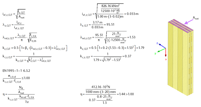
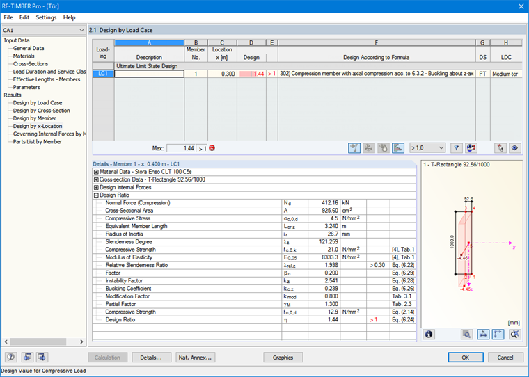
The instability factor that reduces the compressive strength is 0.37. As you can see in Image 02, the resulting design value is 1.44 > 1.00. Thus, the stability design is not fulfilled.
To avoid manual calculation, the equivalent member design can also be performed in the RF-TIMBER Pro add-on module. For this, the "result beam" member type is assigned to the corresponding member in the model (see Image 03). This result beam has no additional stiffness and integrates the surface internal forces into the defined integration area. To design this member in RF-TIMBER Pro, you must assign a cross-section and a material to it. In this case, the stiffness properties of the Stora Enso CLT 100 C5s deviate from the standard. Therefore, it is necessary to create a new user-defined material and adjust the stiffness properties. In order to represent the moments of inertia for the design correctly, a cross-section with an effective width must be created. This can be calculated using the bending stiffness and the cross-section height (see Image 03).
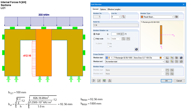
To obtain the same bending stiffness for the homogeneous member, we need the cross-section of b/h = 92.56 mm / 1,000 mm. Thus, the correct moment of inertia is determined when performing the buckling analysis. However, since the applied compression area Anet is too large in this case, it has to be reduced for the design. This reduction may be achieved by adjusting the effective length lef, for example. For this, the effective length lef,z,TIMBERPro is defined in Excel using the target value search, which results from the adjusted effective instability factor kc,z,ef (see Image 04).
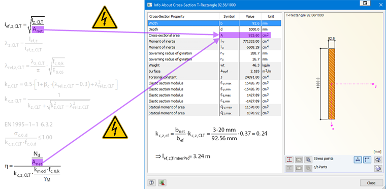
This way, the adjusted effective length considers the cross-section area differently from the effective cross-section in the buckling analysis. The design ratio is identical to that of the manual calculation (see Image 05).
If bending moments are present in addition to the axial force (due to wind, for example), this can also be taken into account in RF-TIMBER Pro with this procedure, since the correct section modulus Sz is already considered for the bending stress. In the case of biaxial bending, the km factor can be additionally multiplied by the factor bef/bnet in the National Annex settings in order to determine the elastic section modulus Sy correctly.