


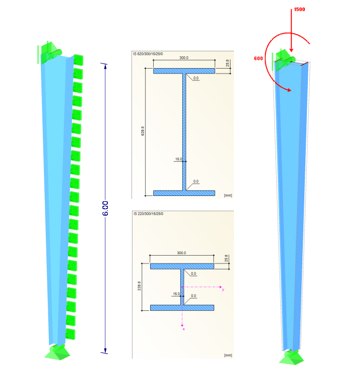
System
Cross-Sections: IS 220/300/15/25/0 (column base), IS 620/300/15/25/0 (column head)
Material: S 355 (DIN EN 1993-1-1)
Column height: 6.0 m
On the tension side of the cross-section is a continuous support in the Y-direction (lateral rotation axis).
Loads
Design loads:
NEd = 1,500 kN
MEd = 600 kNm
Cross-Section Classification
With the existing design loads, the cross-section does not reach the ultimate limit state curve. Therefore, the internal forces must be increased up to the ultimate state.
For this, there are two options:
- Linearly increase all internal forces until the ultimate state is reached (see Image 02 left, the second option [default] in Details)
- Increase only MEd to reach the ultimate state (see Image 02 [right], the first option in Details)

Both options and methods lead to very different results: from a maximum elastic design in the top third to a completely possible plastic design ratio of the cross‑section over the entire column height.
In the present stability failure, no increment of the axial force arises; only an increment of the moments due to deformations and the second‑order analysis. Therefore, the second option is selected.
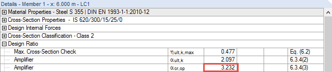
Minimum Amplifier αult,k
In this case, the cross‑section design ratio is determined using the linear plastic interaction (see [2] Eq. [6.2]). This must be activated in Details, since RF‑/STEEL EC3 performs the design for the cross‑sections of Class 1 or Class 2 according to Eq. (6.31) or (6.41) of [2] by default.
In compliance with Section 6.3.4 (2) in [2], it may be necessary to calculate the minimum load amplifier αult,k to reach the characteristic resistance in the main plane with all the effects of imperfections and the second‑order analysis.
The check, as far as deformations affect the internal forces, is determined according to Equation (5.1) in [2]:
In this case, αcr should be determined by RF‑/STEEL EC3 and RF‑/STEEL Warping Torsion. The best way is to generate a separate module case and define intermediate lateral restraints for the set of members in order to enforce the first mode shape with "buckling in the major axis direction".
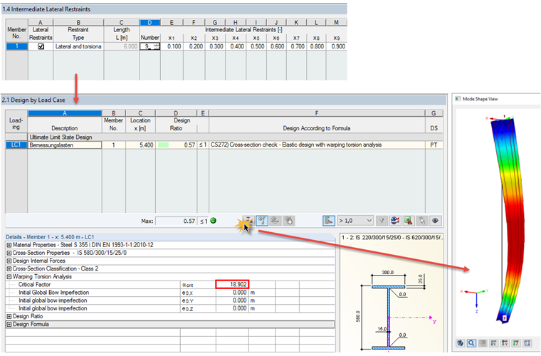
αcr = 18.90 >10
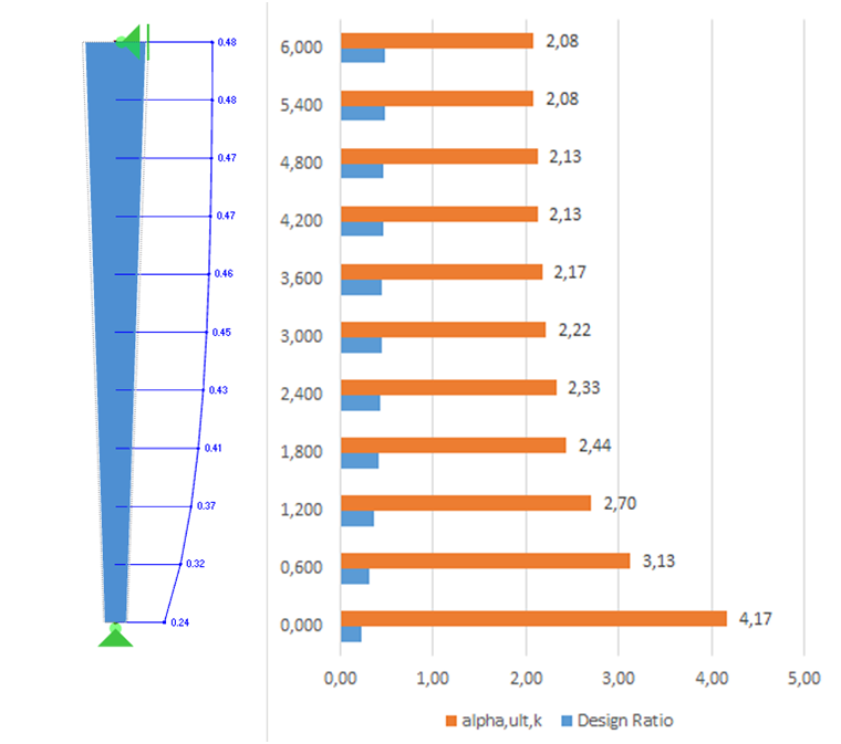
The cross‑section design ratio and thus the minimum load amplifier αult,k can be calculated with the internal forces according to the linear static analysis. The following ratios and factors then arise along the member length.
Slenderness of Structural Component and Reduction Factor χop
The determination of the reduction factor χop requires the slenderness ratio λop to take into account flexural buckling or lateral-torsional buckling. This is calculated according to Equation (6.64) in [2]:
where
αult,k is explained above,
αcr,op is the minimum amplifier to reach the elastic critical load with regard to lateral or lateral torsional buckling.
During the design according to 6.3.4, the RF‑/STEEL EC3 solver determines the minimum load amplifier to reach the elastic critical load of the structural component with regard to lateral or lateral torsional buckling. The properties of the underlying structural system are specified in Windows 1.4 and 1.7 as follows.
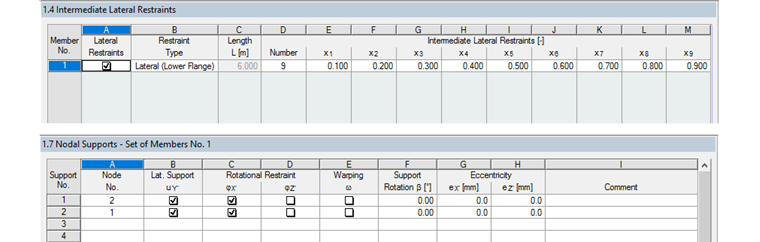
Based on the reference literature, elastic warping restraints were waived, although they would be justified due to the base plate and also the present restraint on the column head. The calculation result is:
Thus, it is possible to determine the slenderness of the structural component according to [2] 6.3.4:
The buckling curve can be selected in compliance with the National Annex (NDP to 6.3.4 [1]) according to Table NA.4:
Buckling, Table 6.2 (welded I-section, tf < 40 mm, buckling in y): BC "c"
Lateral-torsional buckling, Table 6.4 (h/w = 2.07 > 2): BC "d"
In the case of combined effects, the following minimum load amplifier should be used:
χop,z = 0.659 (Eq. 6.49)
χop,LT = 0.684 (Eq. 6.57)
χop = min {χop,LT; χop,z}
χop = 0.659
Component Design
The actual design is performed according to [2] 6.3.4 (2) Equation (6.63):
Adjustment of the equation in terms of the design ratio: