


Ultimate limit state
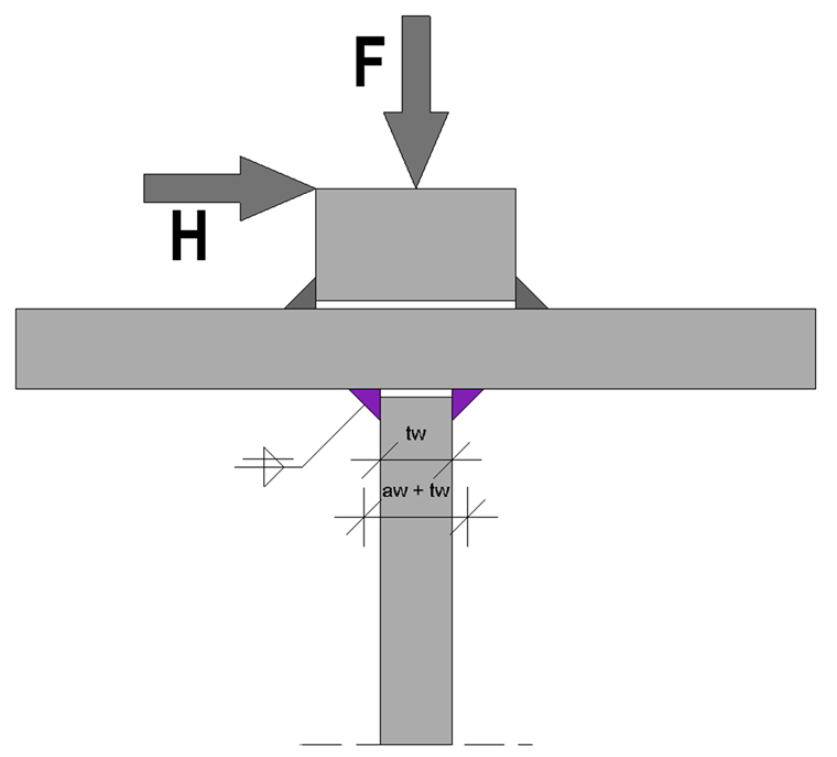
The applied loads cause both horizontal and vertical wheel loads that must be considered in the design. An eccentric wheel load application of the vertical wheel loads is not considered in the ultimate limit state design, and therefore no additional torsional moment occurs.
In the following text is a set of formulas for the stress and design calculation.
Stresses Due to Wheel Load
Weld Design
Fatigue limit state
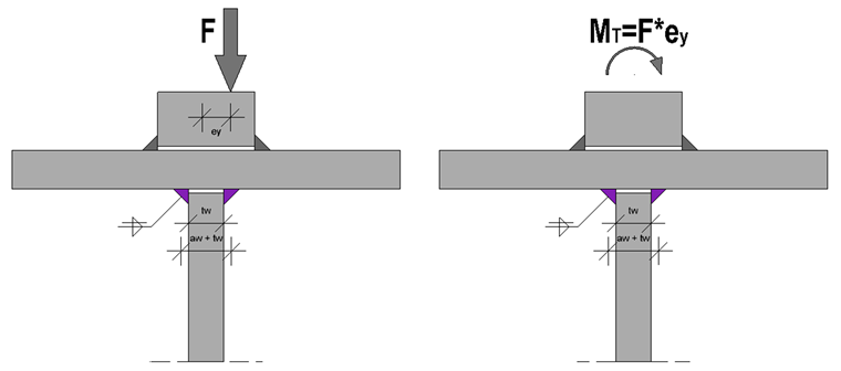
In contrast to the ULS, the stresses resulting from horizontal loads are neglected; thus, only the vertical wheel loads are taken into account. However, depending on the existing damage class and the National Annex used, the eccentric wheel load of 1/4 of the rail head width must be considered. Thus, an additional torsional moment occurs, which must be transferred by the rail welds first, and then by the top flange, the web and finally by the web welds.
The rail welds must transfer this torsional moment almost entirely. On the other hand, the effect of the torsional stiffness of the top flange should be considered for the welds on the web as this has a crucial influence on the web bending and thus on the stress in the weld.
When determining the torsional constant of the top flange, [2] only assumes the top flange as long as the rail is not rigidly fixed. Only in that case is the torsional moment determined from the rail and the flange. Another approach is described in [5], where the individual torsional stiffness components of the rail and the flange are added together so it is possible to achieve higher stiffness of the top flange. However, this approach is not provided in [2].
It is necessary to combine two stress components for the design of the web fillet welds. There are the stresses due to the centric wheel load and the stresses due to the torsional moment. The full torsional moment MT is partially absorbed by the top flange; thus, the component Mweb due to the web bending remains for the weld design.
Finally, it should be noted that this calculation procedure and description only applies to the double fillet welds between the top flange and the web. If the welds on the bottom flange and the web should also be designed as fillet welds, the wheel load effects are negligibly small due to the existing length of the applied wheel loads. In this case, the stress components due to bending or shear stress as well as the minimum thicknesses are governing.
In the following text is a set of formulas for the stress and design calculation.
Stresses Due to Centric Wheel Load
Stresses Due to Eccentric Wheel Load
Resulting Stress in Weld
Designs
Summary
The three technical articles about various welds of crane girders explain this topic in detail. In the practical implementation in individual cases, it should be decided in particular whether to apply the torsional stiffness of the top flange as an addition of the individual components of the rail and the flange, or the flange only.