


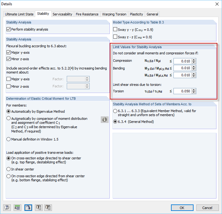
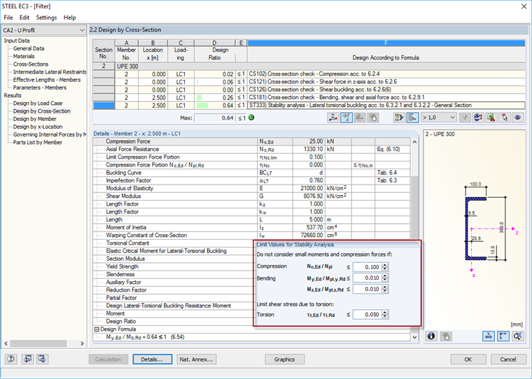
The filter options should be used to permit for design in the case of design problems due to a non-regulated stability analysis of certain cross-sections and load situations, and to neglect the problematic internal forces by using freely definable limits. The limit values can be defined regardless of the default setting in the dialog box shown in Image 01.
Application and Example
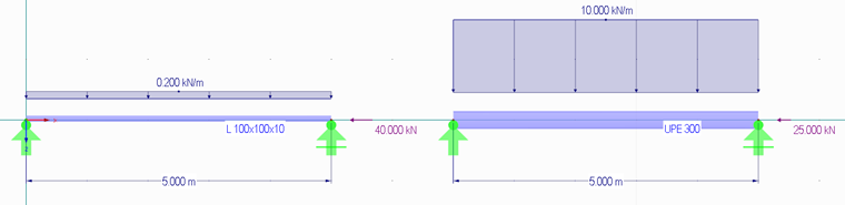
In the following text, two simple examples are provided to explain the application. There are two single-span beams with a length of five meters each. Both are made of S235 structural steel. The left beam is the angle section L 100 × 100 × 10, the right one is the channel section UPE 300. The load is shown in Image 02.
If you try to perform the design directly in RF‑/STEEL EC3, using the German National Annex [2] to Eurocode 3, both beams are considered as non-designable.
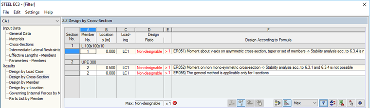
No interaction according to 6.3.3 of EN 1993 [1] is possible for both the L-section and the channel section, since the cross-sections must be double symmetric. Similarly, the design according to 6.3.4 of EN 1993 is also not possible since only I-sections are permitted here. It would be possible to perform the design according to the second-order analysis in RF-/STEEL Warping Torsion. However, the small bending moment on the L-section and the small compression axial force on the channel section are to be neglected in this example.
In this case, the problem is that by neglecting the axial force on the channel section, for example with a limit of 10%, the axial force on the L-section would be excluded, which must be used on the L-section for the buckling design. The bending moment on the channel section may also be neglected the other way around, by neglecting the bending moment on the L-section. In this example, the correct procedure is to create two module cases and design the members separately.
Thus, two cases are considered in RF‑/STEEL EC3:
- Design of the L-section and neglecting the bending moment
- Design of the channel section and neglecting the axial force
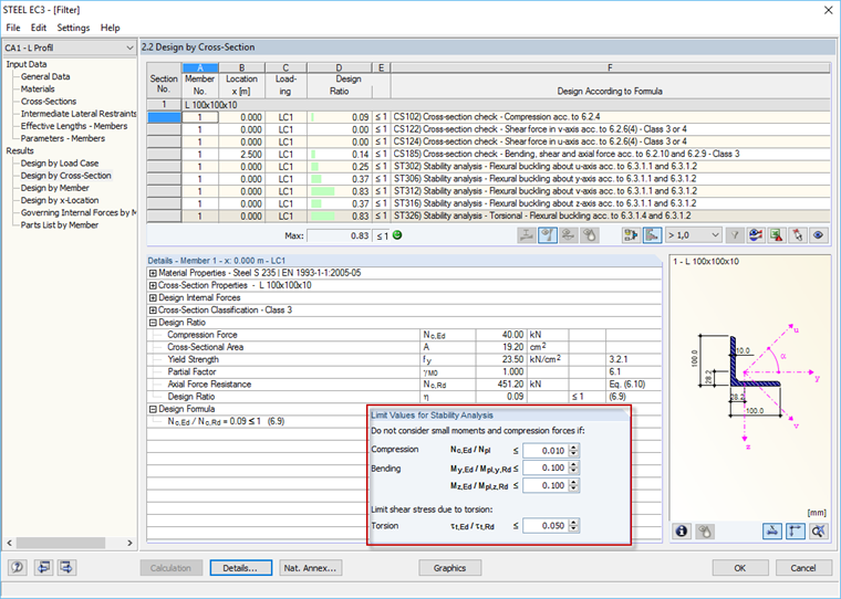
For Case 1, the limit values for neglecting the moment are increased to 0.100. The buckling design is now performed.
For Case 2, the limit values for neglecting the axial force are increased to 0.100. The lateral-torsional buckling design is now performed.
References
[1] EN 1993-1-1. (2010). Eurocode 3: Design of Steel Structures – Part 1-1: General Rules and Rules for Buildings, EN 1993-1-1:2010-12.
[2] DIN EN 1992-1-1. (2015). National Annex – Nationally Determined Parameters – Eurocode 2: Design of Steel Structures – Part 1-1: General Rules and Rules for Buildings, DIN EN 1993-1-1/NA:2015-08.