


DIN EN 1993-1-8 [3] provides a model for the calculation as well as the classification of the connection stiffness and manages the resulting modeling of the semi-rigid joint in the structural model.
In practice, bending-resistant connections are usually defined as rigid in the determination of internal forces or in the structural model. The moment-rotation characteristics of the connection are thus not considered in the determination of internal forces. In most cases they have to be considered, however, depending on the stiffness of the structure, according to the standards in structural analysis.
In the following text, the effect of the slip of the connection on the design results of frame structures will be shown in an example.
Structural System
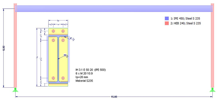
This is about a two-hinged frame with a span of 15.0 m and a height of 6.0 m plus a 0.8 m attic.
For the first design step with rigid connections, the cross-sections as shown in Image 01 are applied. Structural steel S235 according to DIN EN 1993-1-1 [2] will be used.
Loading
This will be calculated with the following simplified load assumptions:
- Load width (distance from the frame) = 5.00 m
- Self-weight roof structure g = 0.40 kN/m²
- Snow load s = 1.30 kN/m²
- Wind load walls w = 0.60 kN/m² (cp = 0.8 and -0.5)
- Imperfections (in the frame plane) according to DIN EN 1993-1-1
ULS Design with Rigid Frame Joint
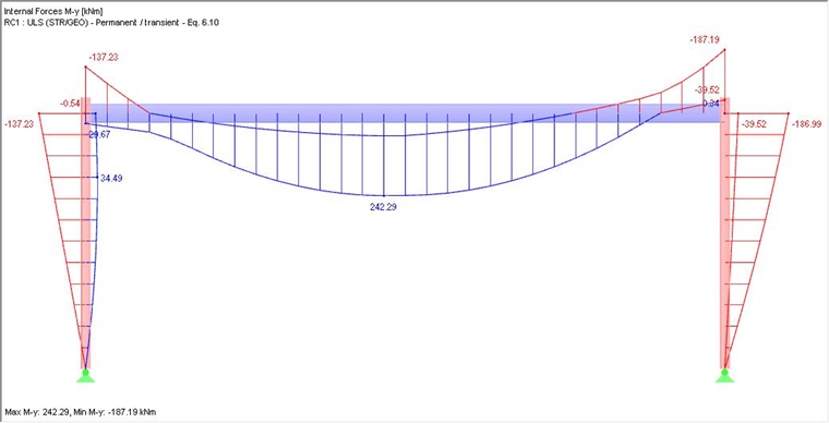
The calculation of the internal forces in the frame plane is performed according to the second-order analysis and with imperfections (inclination and precamber). The enveloping of internal force My is shown in Image 02.
For the beam design with RF-/STEEL EC3, a lateral and torsional restraint at the member ends and a lateral support of the upper chord are applied at one-third division points.
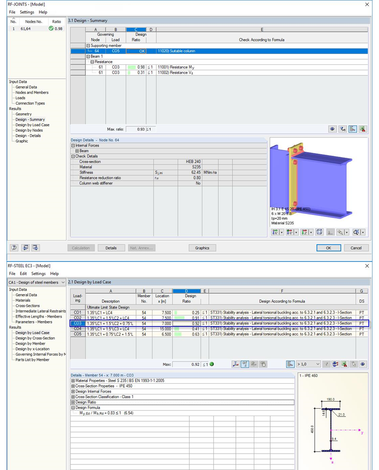
The design of the frame joint is performed with RF-/JOINTS Steel – DSTV. Types IH3.1 and M20 will be used. No design of the connection according to [1] is possible with the existing internal forces.
Therefore, the beam section has to be increased to IPE 500 and the connections have to be selected as shown in Image 01 to analyze the serviceability limit state.
ULS Design with Semi-Rigid Frame Joint
The requirement to consider the moment-rotation characteristics in structural analysis results from the classification of the connection according to DIN EN 1993-1-8.
For a movable frame, the "deformable" classification applies if:
For the currently designed connection IH 3.1 E 50 20 6xM20 10.9 (see Image 01) without stiffener and the column HE-B 240, this results in:
The stiffness of the structure is calculated according to EN 1993-1-8, Section 5.2.2.5 as follows:
The connection can thus be classified as deformable:
3,374 kNm/rad < Sini = 72,270 kNm/rad < 168,700 kNm/rad
Due to the expected redistribution of internal forces to the span moment, a calculation and design with the original IPE 450 can now be attempted again.
The calculation of the internal forces in the frame plane is again performed according to the second-order analysis and with imperfections (inclination and precamber) as well as in consideration of the moment-rotation characteristics of the connection. The application is carried out according to DIN EN 1993-1-8 Sec. 5.1.2(4), simplified with a linear rotational spring with Sj,ini/2. The enveloping of internal force My is shown in Image 04.
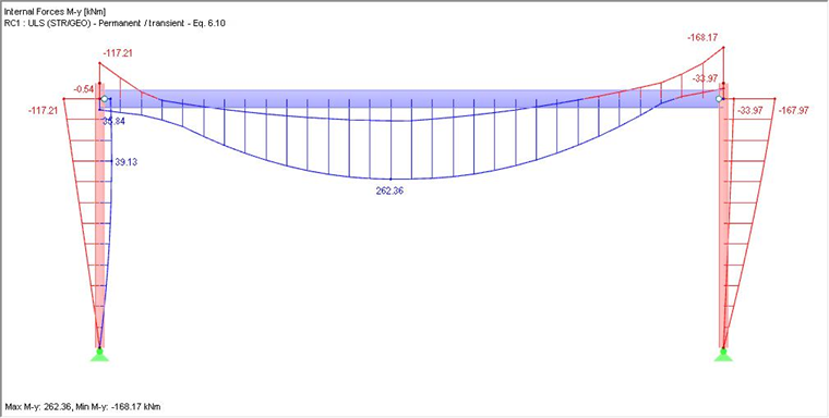
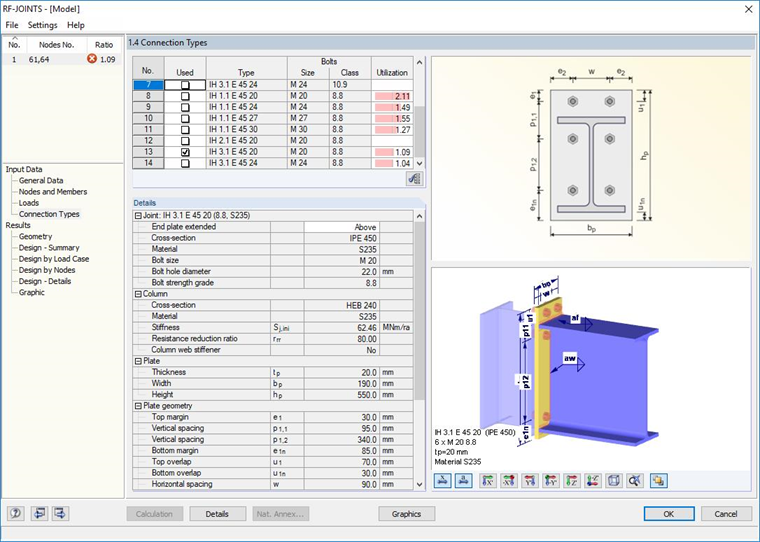
Due to the consideration of the rotation stiffness, it results in a reduction of corner moments of about 10%. The design of the connection with RF-/JOINTS Steel – DSTV results in a positive design for type IH 3.1 E 45 20 6xM20 8.8. The original section IPE 450 can also be designed as sufficiently resistant (see Image 05).
SLS Design with Rigid Frame Joint
Only the design of the horizontal deformation of the frame will be performed here. The limit value is defined with wh,max = h / 150 = 680 / 150 = 4.53 cm.
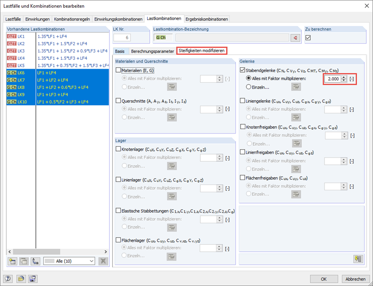
Due to the smaller load level for the SLS, it can be assumed that the moments are below 2/3 Mj,Ed and therefore, the elastic initial stiffness of the connection can be applied for the deformation analysis. This can be done via the modification of the stiffness for the relevant load combinations in the calculation parameters (see Image 06).
By applying Sj,ini, it results in deformations in the X-direction of 4.73 cm (see Image 07).
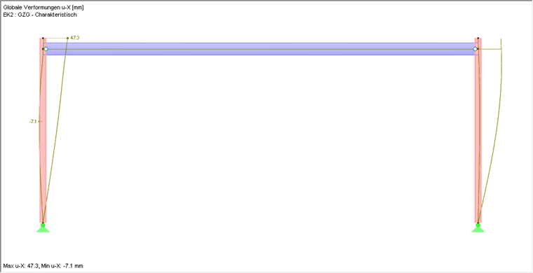
The design is thus as follows:
wex / Wh,max = 4.73 / 4.53 = 1.04
Conclusion
The consideration of the moment-rotation characteristics of the connection results in a more realistic display of the structure and a more economical design with a material savings of about 10% in this example.
Furthermore, it is necessary to apply the elastic initial stiffness for the deformation analysis for the respective load combinations in order to perform the serviceability limit state designs in terms of cost-effectiveness.