This example is described in [1]. The design according to Section 6.2 of DIN EN 1993‑1‑8 applies to I- and H-sections and is not applicable in this case. Therefore, the CIDECT method described in [2] and an FEA model are used.
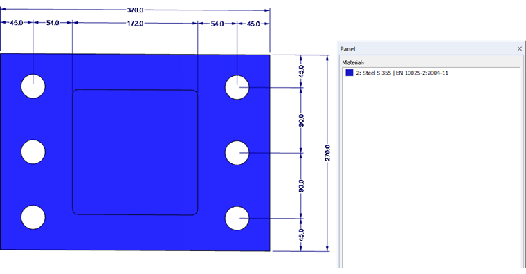
System
- Cross-section: HE-A 180
- End plate: tp = 35 mm
- Material: Steel S355 according to DIN EN 1993-1-1, Table 3.1

The FEA model is modeled by means of surface elements, member elements for the bolts, and a solid to represent the contact of the two end plates. Nonlinearities are defined for the contact solid. "Isotropic plastic 2D/3D" is selected as the material model for the end plates (requiring the RF‑MAT NL add-on module). This material model shows an isotropic material behavior in the elastic zone. The plastic zone is based on the yielding according to the distortion hypotheses according to von Mises with a defined yield strength of the equivalent stress of 35.5 kN/cm².
Internal Forces
The governing design force in the bottom chord resulting from the determination of internal forces is NEd = 1,491.5 kN (tension). If this is converted to the perimeter of the hollow cross-section (center line), the line load is 2,211.60 kN/m.
Design
The design should include the partial design of the ultimate limit state of the end plate and the calculation of the loading of one bolt (including contact force).
Ultimate limit state of the end plate
The resistance of the end plate under bending is determined according to Equation 8.6 with the CIDECT method:
With Equation 8.5
this results in:
Thus, it results in a ratio of:
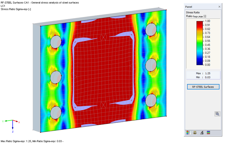
The evaluation of the stresses in the end plate on the FEA model with the RF‑STEEL Surfaces add-on module produces an adequate result.
Bolt Resistance
For the bolt design, it is essential to determine the resistance including the contact forces. The calculation is performed according to Equation 8.7 with the CIDECT method as follows:
With Equation 8.9
this results in:
Thus, it results in a ratio of:
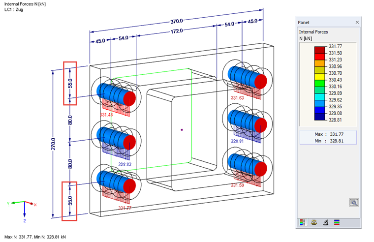
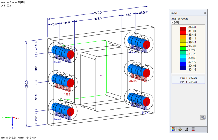
The evaluation of the member internal force N in the FEA model results in a maximum bolt force of 343 kN in the central bolts and is, therefore, slightly higher than the analytical result.
In [2], the validity of the design criterion is linked to the fact that the outer bolt axes in the top plate connection are not located outside the corners of the hollow section. Figure 8.5 in [2] does not show the axis of the bolt, but the bolt hole as lying within the dimensions of the hollow section.
Increasing the edge distance to e = 55 mm results in a redistribution of the bolt forces towards the outer bolts and a homogeneous distribution in terms of the process.