If you perform the punching shear design in RF-PUNCH Pro on a concentrated load application location, the punching load can be determined directly from the axial force of a column, the support force, or directly from the nodal load.
Determination of Punching Load from Shear Force Distribution in Surface
It is difficult to transfer the punching load directly from the support forces in case of linear load application locations (wall corner and wall end). For these application cases, RF-PUNCH Pro uses the shear force in the critical perimeter of the analyzed surface and determines the punching load, which is then applied for the design. The method for determining the punching load on wall corners and wall ends was described in this technical article.
Punching Load for Flat Slabs
However, it is also possible to determine the punching load from the "smoothed" or "unsmoothed shear force over the critical perimeter" for flat slabs located on nodal supports or columns.
In the commentary to EN 1992-1-1 [2], the section "To (5)" indicates that the load components from a uniformly distributed load within the critical perimeter must not be neglected or subtracted when using flat slabs.
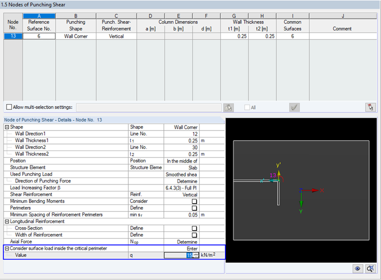
Considering Surface Load Inside Critical Perimeter
RF-PUNCH Pro has offered the option to consider the surface load within the critical perimeter since program version RFEM 5.20.01. This option is available in Table "1.5 Nodes of Punching Shear".
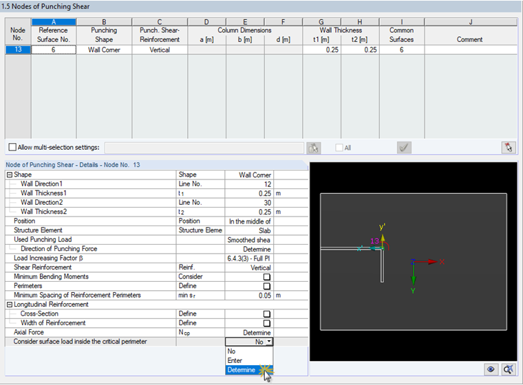
The following three options are available:
- Do not consider the surface load inside the critical perimeter
- Enter the surface load inside the critical perimeter
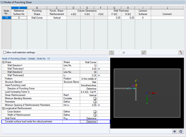
- Determine the surface load inside the critical perimeter
Distingushing Between Options "Enter" and "Determine"
RF-PUNCH Pro is able to determine the surface load inside the critical perimeter automatically by means of the load distribution on the surface in the respective load case.
The intermediate results for the automatic determination of the surface load inside the critical perimeter are documented in Result Table "2.1 Punching Shear Design" in the "Applied Maximum Shear Stress" section. The applied size of the surface is also documented here.
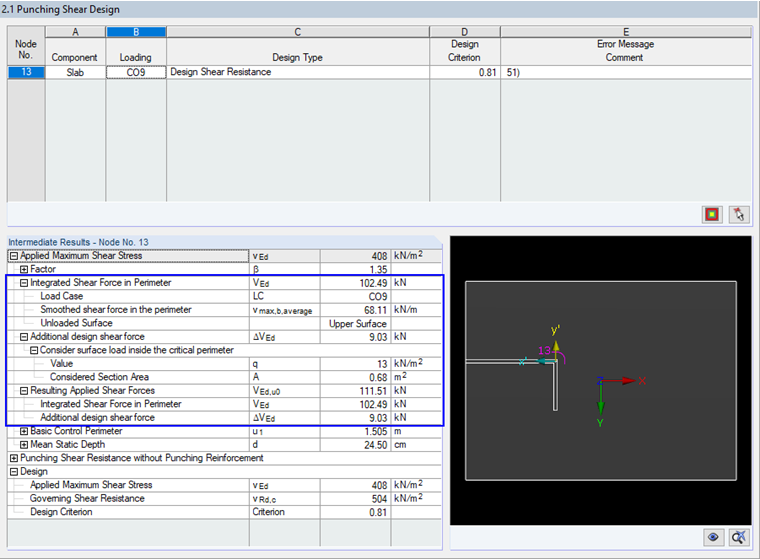
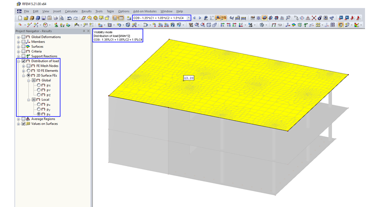
The surface load applied in the add-on module can be checked graphically by displaying the "Load Distribution" for the governing CO (in this case, CO9; see Results in Image 03) for the 2D elements. You can find the load distribution in the Results navigator when the result display is activated for CO9.
If you select the "Enter" option, the dialog box changes and you can specify the load value directly.
Distingushing Between Load and Result Combinations
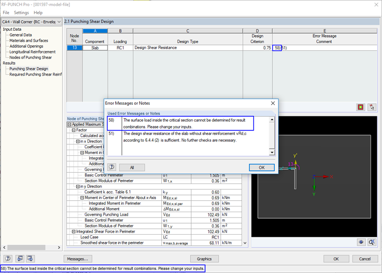
You can use the "Determine" option if there is a clearly defined load. This is the case if load combinations (COs) have been selected for the design in the "1.1 General Data" dialog box. If result combinations (RCs) are selected instead of COs, there is no clear load situation. In this case, message 58) will be displayed, which says that the surface load inside the critical section cannot be determined for result combinations.