


The following options are available to create the cross-section:
- Creating elements automatically and continue editing
- Considering lines of a DXF template as center lines of elements with assigned thickness
- Creating a DXF template for further editing
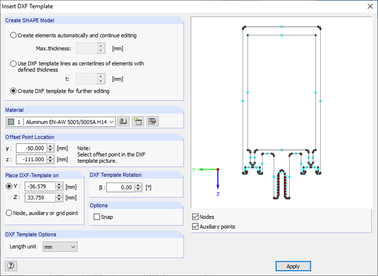
The automatic generation of elements is useful for simple cross-section geometries. SHAPE-THIN tries to create center lines for parallel lines and then set the elements between the intersection points. Only elements are generated which do not exceed the maximum thickness defined in the "Max. thickness" text box.
If the cross-section geometry is available as a gravity line model, you can consider the lines of the DXF template as the center lines of the elements. The thickness defined in the "t" text box is assigned to all elements.
The DXF file is additionally created as a background layer for the above-mentioned options for creating the cross-section. Importing the DXF file as a background layer is only possible with the "Create DXF template for further editing" option.
You select the material from the material library and the length unit of the DXF template using the "Length unit" drop-down list. The DXF template can also be rotated. Furthermore, you can enter the offset point location manually in the "y" and "z" text boxes or transfer it in the graphic by selecting the node or the snap point. You can then position the DXF template in the SHAPE-THIN work window with your mouse. You can also specify the position of the DXF template in the "Y" and "Z" text boxes.
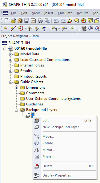
The background layer can be shifted, mirrored, rotated, or stretched. To access these functions, select the "Edit" → "Background Layers" menu or use the shortcut menu in Project Navigator – Data.
Furthermore, you can import a background layer by clicking "New Background Layer". In contrast to the DXF import, where a new file is created, the background layer is inserted into the current file.
Elements can be created later, based on the background layer. To do this, open the "Set elements according to the DXF template" dialog box under "Edit" → "Set elements with DXF template".
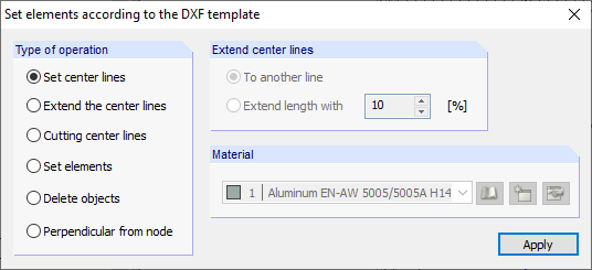
First, use the "Set center lines" option to create the center lines by clicking the opposite contour lines. If there is no intersection between the center lines, you can use the "Extend the center lines" option to draw the lines. Click to enlarge the selected part of the line.
The "Set elements" option creates elements on center lines that have an intersection point on both ends. Click the corresponding center lines.
For contour lines that are not parallel, you have to set the elements manually, because SHAPE-THIN can only create center lines as well as elements for parallel lines. The background layer is a modeling aid. For lines and nodes of the background layer, the object snap of nodes, intersection points, the center, and so on, is available.
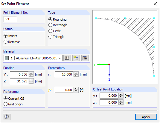
Irregularities in the cross-section geometry can be displayed as point elements. They can be added as rounding, rectangle, circle, or triangle, or removed from member surfaces. You can set point elements using "Insert" → "Cross-Section Data" → "1.5 Point Elements", the table with the same name, or using the corresponding button in the toolbar.
For symmetric cross-sections, we recommend modeling only one part of the cross-section and creating the other parts by mirroring.
Cross-section modeling based on a DXF file is shown in the video, which you can find in the top left corner of this article.
