You can open the add-on module via the RFEM menu item Add-on Modules → Others → RF-MOVE Surfaces. Alternatively, you can open it in the Data tab of the Project Navigator by clicking the entries Add-on Modules → RF-MOVE Surfaces.
Input
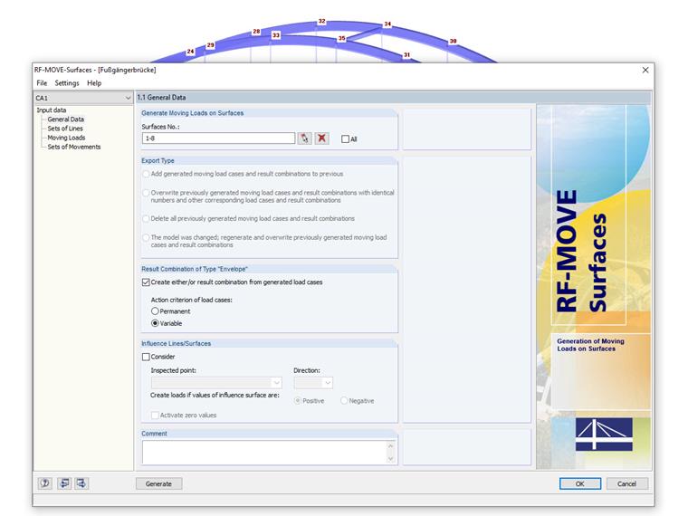
First, you specify the surfaces on which the moving loads are to be generated.
If moving loads are already available in the structure, you have to make further entries in the "Export Type" window section. If this is not the case, this section is grayed out, as in our case.
Then, the check box under Result Combination of Type "Envelope" allows you to generate a result combination from the load cases of the moving loads. The Variable option is selected as the action criterion of the load cases.
The "Influence Lines/Surfaces" window section allows you to consider influence lines and surfaces that have been determined by the RF-INFLUENCE add-on module. The amount of data can be reduced, as only unfavorable load cases are generated. In our example, this check box is not activated.
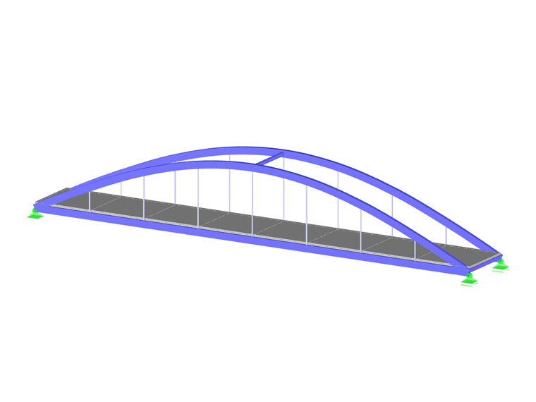
Next, you define the distance that the moving loads should cover. For this, a set of lines must be created. We recommend defining the "lane" in advance in the RFEM model.
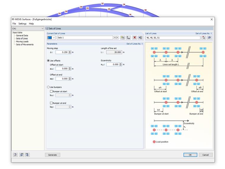
In the "List of Lines/Set of Lines No." input field, you can manually enter the numbers of the lines representing "guiding lines" for the moving load. The order of the numbers specifies the moving direction.
Of course, the lines can also be selected graphically in the work window. Again, it is important to ensure that the lines are clicked in the correct order.
The "Parameters" section manages global specifications for the load case generation.
The "Moving step" controls the equal distances by which the loads move over the surfaces. The smaller the moving step, the more load cases are created. Furthermore, an offset and/or a bumper can be applied.
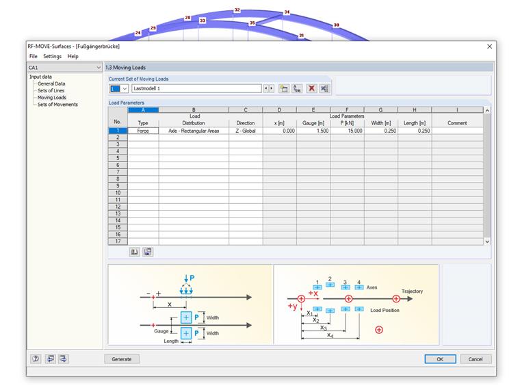
This "Moving Loads" window manages the parameters of the moving loads. Different loads can be combined in one load model. The module assigns defined load models to the sets of lines and creates individual load cases based on these data.
Then, the load can be defined as force or moment, and the load distribution is selected. Several options are available.
In this example, the load distribution for "Axle – Rectangular Areas" is selected. The advantage is that the load is distributed as a block load pair on two surface loads in a distance of the gauge, and thus, contrary to a single load, singularities can be avoided.
Since composing moving loads usually involves time and effort, they can be saved in the load model library so that they can also be used for other projects. In addition, a large number of load models is already stored in the database.
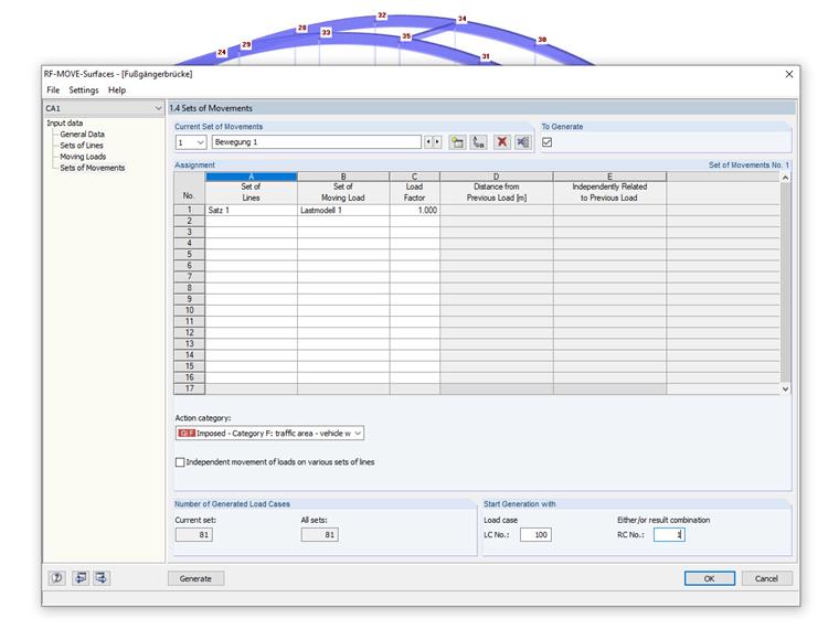
The last window, "Sets of Movements", connects the geometry input of the sets of lines with the load input of the moving loads. Thus, the window specifies which load sets move on which sets of lines.
In most cases, a single set of movements is sufficient, as in our example.
Set 1 is applied as the set of lines, and Load Model 1 as the moving load. Imposed loads of category F are selected as the action category.
Generation and Results
The various load cases can be generated by a single mouse click on the "Generate" button. At the end of the generation, the numbers of the created load cases and result combinations are displayed as a note; in our example, it is 81.
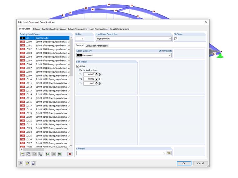
RF-MOVE Surfaces does not provide any result windows. The loads generated in the individual load cases can be checked as usual in the graphic, the editing dialog boxes, or the "Loads" table below. They entered the corresponding tables as free concentrated loads, free line loads, or free polygon loads.
Documentation
The add-on module's data is not managed separately in the printout report. The generated load cases, including loads, are transferred to RFEM, where they can be integrated into the documentation.