Structure stability is not a new phenomenon when referring to steel design. The Canadian steel design standard CSA S16 and the most recent 2019 release is no exception. Detailed stability requirements can be addressed with either the Simplified Stability Analysis Method in Clause 8.4.3 or, new to the 2019 standard, the Stability Effects in Elastic Analysis method provided in Annex O [1].
Clause 8.4.1 [1] lists the stability requirements which the structural design should address using either method. These include deformations contributing to the structure, second-order effects including P-Δ and P-δ, global and member geometric imperfections, stiffness reduction accounting for member yielding and residual stresses, and lastly, uncertainty in the structure’s stiffness and strength.
Clause 8.4.3 – Simplified Stability Analysis Method
With the simplified stability analysis method given in 8.4.3 [1], only a couple requirements are listed.
Geometric Nonlinearities
The first includes member second-order effects, or P-Δ, which can be directly considered in the analysis. A second-order analysis calculation method is most common with many structural analysis software programs today. The alternative is to amplify all member axial loads and bending moments obtained from a first-order analysis by the factor U2 defined in 8.4.3.2(b) [1]. This approach may be better suited for hand calculations or if the structural analysis software does not include P-Δ effects automatically.
Geometric Imperfections
Notional lateral loads are the second item listed under the simplified method in Clause 8.4.3.3 [1]. This applied load is equal to 0.005 times the total factored gravity load at the considered story and should be distributed similarly to the gravity load. Notional loads are always applied in the direction which generates the greatest destabilizing effect. This means such loads should be applied in the same direction as a lateral wind load to generate the highest deformations and internal forces on the structure.
Annex O.2 – Stability Effects in Elastic Analysis
As an alternative to the simplified stability analysis approach above, engineers can utilize Annex O.2 to satisfy the stability requirements set forth in Clause 8.4.1 [1]. This approach was added to the 2019 standard and has many similarities to the US steel design manual AISC 360-16 Ch. C Direct Analysis Method.
Geometric Nonlinearities
Geometric nonlinearities, or second-order effects, are addressed in O.2.2 [1]. Like the simplified method, a second-order analysis can be carried out directly which includes the effects of loads acting at members’ displaced points of intersections (P-Δ effects). Additionally, the effects of axial loads acting on the deflected member shape along the length should be considered (P-δ). There are provisions given in O.2.2 [1] where P-δ can be neglected entirely. On the other hand, if P-δ is included directly in the analysis, the factor U1 can be set to 1.0 used in Clause 13.8 - Axial compression and bending member design [1].
Geometric Imperfections
Member geometric imperfections such as member out-of-straightness or local geometric imperfections such as element out-of-straightness for members do not need to be considered when designing to Clause O.2 [1]. However, global geometric imperfections should be considered with direct modeling or with the use of notional lateral loads. There is the exception, though, that these global geometric imperfections can be neglected for lateral load combinations only if they meet the requirements set forth in Clause O.2.3.1 [1]. Among the requirements are that the structure’s gravity loads are supported primarily by vertical structural elements and that the ratio between maximum 2nd-order story drift to 1st-order story drift using reduced member stiffness according to Clause O.2.4 [1] does not exceed 1.7 at any story level.
When the engineer cannot neglect these imperfections, the first method of direct modeling can be used. Member points of intersection should be displaced from their original locations. The amplitude of this initial displacement is set forth in Clause 29.3 [1] and applied in the greatest destabilizing direction, which for most building structures is a 1/500 tolerance for column out-of-plumbness. The significant problem with this method is the high number of model scenarios that must be considered. Theoretically, four displacements are needed in the four different directions at each story level. If member out-of-straightness effects are also coupled with column out-of-plumbness, this adds many more modeling scenarios to be considered to meet the greatest destabilizing effect.
The alternative and preferred method for global geometric imperfections is to apply notional lateral loads. This method is only permitted when the gravity loads are primarily supported by vertical structural elements. Notional lateral loads were covered earlier in this article and are applied in the same manner as the simplified stability analysis in Clause 8.4.3.2 [1]. However, the amplitude is reduced from 0.005 to 0.002 times the factored gravity load at the relevant story. The reduction in magnitude is permitted in Clause O.2.3.3 as these notional loads account for global geometric imperfections only, whereas notional loads in Clause 8.4.3.2 [1] are also accounting for inelasticity effects and other uncertainties.
Inelasticity Effects
To account for inelasticity effects and to also give consideration for initial member or local geometric imperfections as well as uncertainty in stiffness and strength, reduced member axial and flexural stiffness according to the following equations in Clause O.2.4 [1] should be applied to members contributing to the lateral stability.
- EAr = 0.8τbEA
- EIr = 0.8τbEI
where
- Cf/Cy < 0.5 ; τb = 1.0
- Cf/Cy > 0.5 ; τb = 4Cf/Cy(1-Cf/Cy)
To avoid localized distortions, the standard suggests applying this stiffness reduction to all members. Furthermore, when the shear stiffness (GA) and torsional stiffness (GJ) contribute significantly to the lateral stability, stiffness reduction should be considered. Stiffness reduction should not be used when analyzing drifts, deflections, vibrations, or natural vibrations.
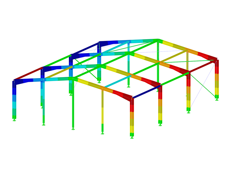
Annex O.2 Application in RFEM 6
The new generation FEA program RFEM 6 incorporates the latest stability requirements of the CSA S16:19 standard according to the Annex O.2 provisions.
Geometric Nonlinearities
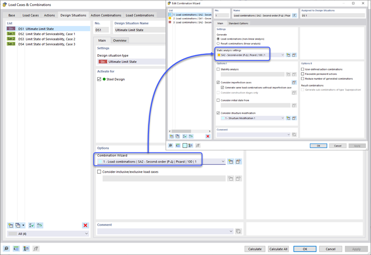
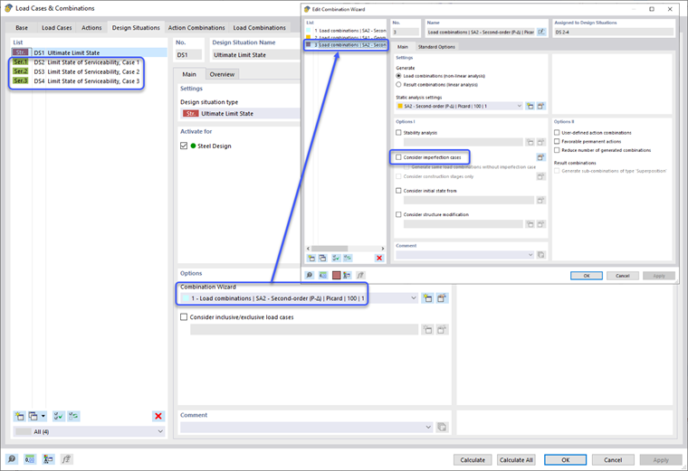
The second-order effects set forth in Clause O.2.2 [1] are directly considered when the static analysis calculation method is set to “Second-order (P-Δ)”. This can be applied in the Design Situation Combination Wizard options. In turn, all load combinations under the Design Situation will be set automatically to a second-order analysis as well. The user has the option to individually modify a load combination’s static analysis settings if preferred.
Not only are P-Δ effects included for the member analysis, but P-δ are also automatically considered. For more information on this topic and verification in RFEM 6, take a look at: Knowledge Base 1759 .
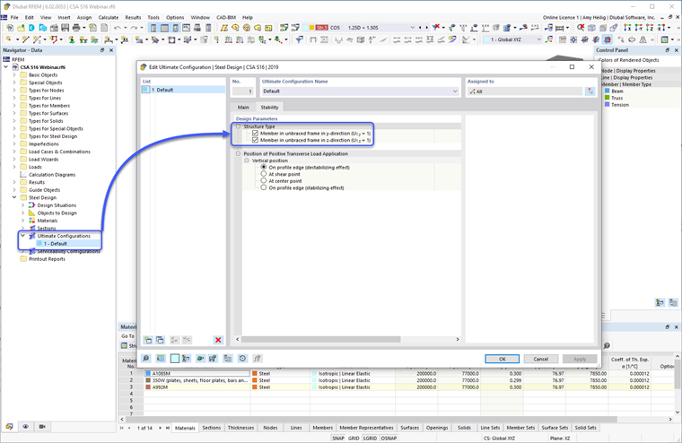
Therefore, the factor U1 can be set to 1.0 specified in Clause 13.8 for the steel member design. This option is found under the Steel Design Add-on – Ultimate Configurations – Stability – Design Parameters.
Geometric Imperfections
The RFEM 6 user has the option to directly model global geometric imperfections by displacing points or nodes of member intersections. However, to ensure this method creates the greatest destabilizing effect, multiple models with various scenarios will need to be carried out. This is rather time consuming and cumbersome.
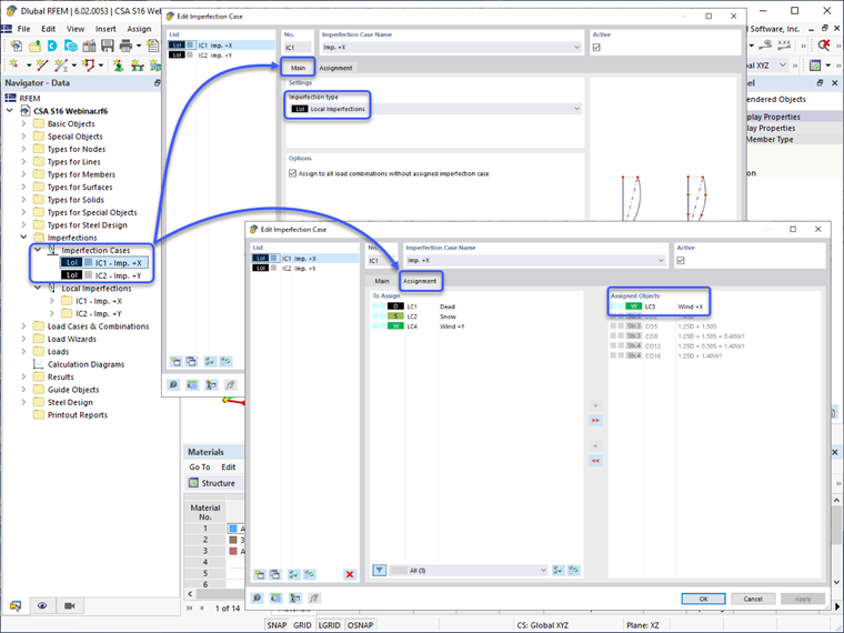
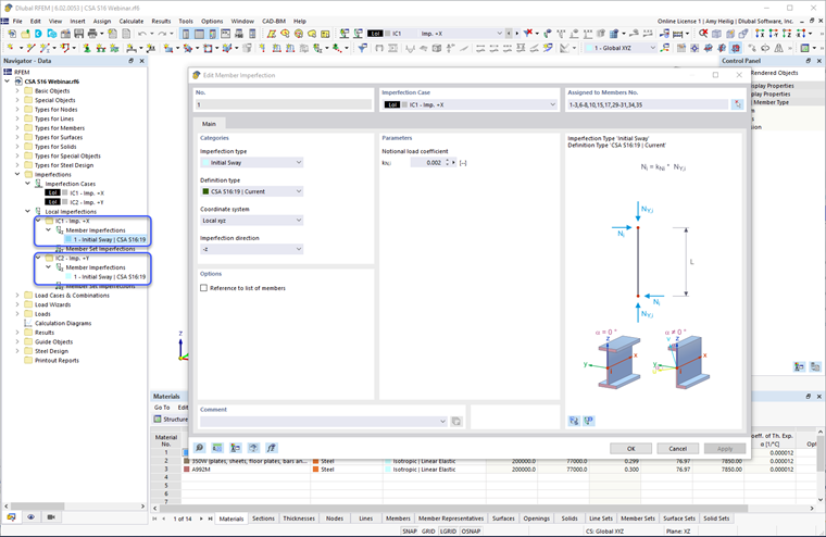
The alternative approach is to apply notional loads with the imperfection options provided in RFEM 6. To begin, Imperfection Cases with the imperfection type set to “Local imperfections” under the Main tab must first be defined. These would typically include cases in the orthogonal directions X and Y, depending on the application of lateral loads such as wind and seismic. The Imperfection Case can then be correlated under the Assignment tab to the specific load cases to produce the greatest destabilizing effect (for example, notional loads in the +X-direction should only be applied with wind loads in the +X-direction).
After the Imperfection Cases are generated, the member imperfections can be defined. The Member Imperfections dialog box includes the CSA S16:19 in the dropdown options. The notional load is applied to the member end (i.e., top of column) with a magnitude equal to 0.002 (or 0.005 if using the simplified stability method) multiplied by the member’s axial force (applied member gravity load). An equal and opposite force is internally applied at the opposite member end to avoid unrealistic base shears. The imperfection definition is applied to the members’ local axes in the same direction as the applied lateral load such as wind or seismic. The definition is further applied to all vertical members in the model.
After the imperfections are applied to the model, the Design Situation is set by default to consider imperfections for all load combinations. Imperfections should be applied to the Ultimate Design Situations but turned off for the Serviceability Design Situations. This can be set by creating a new Combination Wizard definition type, turning off the imperfection consideration options, and applying to the Serviceability Design Situations only.
Inelasticity Effects
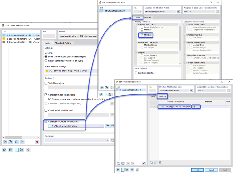
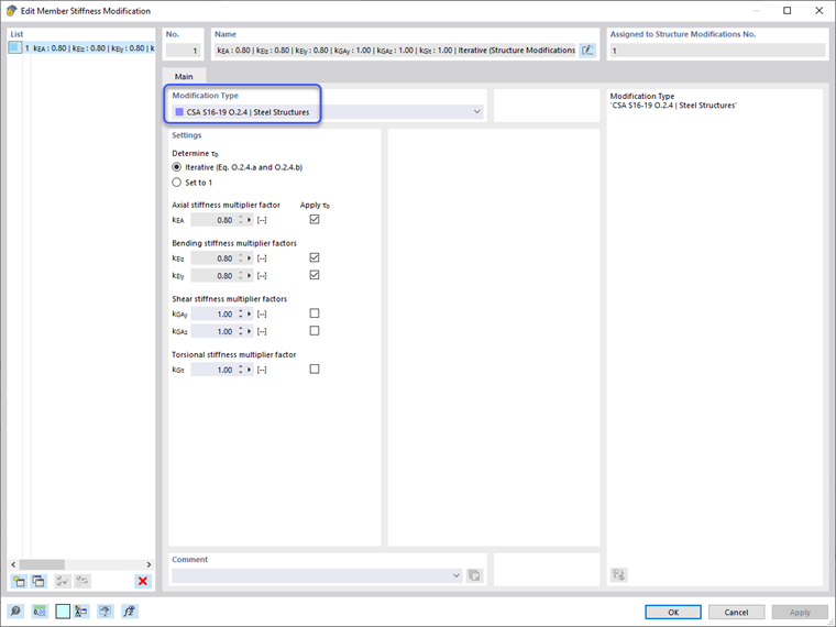
Stiffness reductions are applied to the Ultimate Design Situation only once again through the Combination Wizard definition options and the “Consider structure modification” checkbox. A new structure modification definition can be created. The “Members” checkbox is selected under the Main tab - Materials and Sections. This brings up a new Members tab where the Member Stiffness Modification definition is defined according to the CSA S1-19 O.2.4 | Steel Structures. This definition type allows the program to either calculate the τb reduction factor automatically, or a generalized 1.0 value can be set for all members. Additionally, the 0.8 factor can be applied to the various member stiffness types. The user can determine if the τb and 0.8 factor should be applied only to the member axial and bending stiffness or if shear and torsional stiffness should also be considered. Once the stiffness modification properties are input, the definition can be applied to specific members or the term “All” can be set to apply to all members in the model.
Because member stiffness reduction should not be considered for serviceability design (for example, deflection checks), the “Consider structure modification” checkbox should remain unchecked for the Serviceability Design Situation Combination Wizard definition.
After these modifications, all factored load combinations will include the structure modification stiffness reduction while all unfactored load combinations will use the full member stiffness.
Summary
Significant stability design requirements according to Annex O.2 in the Canadian steel design manual CSA S16:19 are fully incorporated in the RFEM 6 analysis workflow. Most notably, these requirements include a second-order analysis, the ability to consider notional loads as imperfections, as well as reduced member stiffnesses. To see this topic demonstrated in a detailed example video, check out the webinar: CSA S16:19 Steel Design in RFEM 6 (USA) .