Superposition of Modal Responses in Response Spectrum Analysis Using Equivalent Linear Combination in RFEM 6 / RSTAB 9

Technical Article on the Topic Structural Analysis Using Dlubal Software

  • Knowledge Base

Technical Article

The response spectrum analysis is one of the most frequently used design methods in the case of earthquakes. This method has many advantages. The most important is the simplification: It simplifies the complexity of earthquakes so far that the design can be performed with reasonable effort. The disadvantage of this method is that a lot of information is lost due to this simplification. One way to moderate this disadvantage is to use the equivalent linear combination when combining the modal responses. This article explains this option by describing an example.

Theoretical Background

For each natural frequency, the response spectrum method determines one modal response by means of the defined response spectrum. In the case of complex systems, there may be a large number of mode shapes to be considered. The subsequent superposition proves to be difficult because in reality, all natural vibrations would not occur in their full magnitude at the same time. In order to consider this fact in the calculation, the individual modal responses are superimposed quadratically. The European design-relevant standard EN 1998-1 gives two rules for this: the method for the square root of the sum of squares (SRSS rule) and the method of the complete quadratic combination (CQC rule) [1].

Applying these rules usually provides realistic and economical results as opposed to simple addition. However, the direction of the excitation and thus the signs of the results are lost during the superposition. In consequence, the results are always given as maximum values in the positive as well as in the negative direction. Corresponding internal forces and moments, for example a corresponding moment at the maximum axial force, are lost. This should be avoided by modifying the SRSS and CQC rule: The formulas will be written as a linear combination instead of a root. This rule was introduced by Prof. Dr.-Ing. C. Katz [2] and is shown below using the SRSS rule as an example.

Standard SRSS Rule

ESRSS = E12 + E22 + ... + Ep2

Modified SRSS Rule - Equivalent Linear Combination

ESRSS = i = 1p fi · Ei     mit     fi = Eij = 1p Ej2

Comparison of Results Using an Example

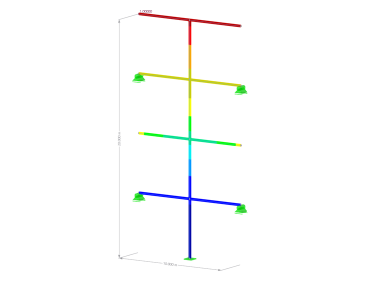
The effect of the equivalent linear combination is explained by a simple two-dimensional steel structure. Three internal forces are considered: axial force N, shear force Vz, and moment My. In the following, it is exemplified using the Response Spectrum Analysis add-on in RFEM 6.

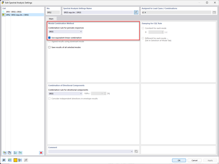
Four mode shapes are calculated in the X-direction and a response spectrum based on EN 1998-1 is used. Activating the equivalent linear combination and selecting the combination rule is done in the "Spectral Analysis Settings" dialog box.

The results of the individual modal responses are analyzed, for example, on node number 5 (on member number 6 → left side) and are listed in the following table.

Response of Mode Shape 1 Response of Mode Shape 2 Response of Mode Shape 3 Response of Mode Shape 6
Axial Force N 1.361 kN -0.246 kN 0.815 kN
Shear Force VZ 0.480 kN -1.635 kN -0.556 kN 1.536 kN
Moment My -2.400 kNm 8.174 kNm 2.781 kNm

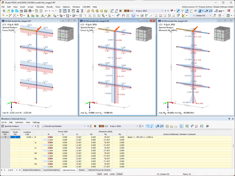
The following values result from the standard SRSS rule.

Axial force - calculated by standard SRSS rule

NSRSS = (1.361 kN)2 + (-0.246 kN)2 + (0.815 kN)2 + (-2.322 kN)2 = 2.823 kN

Shear force - calculated by standard SRSS rule

Vz,SRSS = (0.480 kN)2 + (-1.635 kN)2 + (-0.556 kN)2 + (1.546 kN)2 = 2.367 kN

Moment - calculated by standard SRSS rule

My,SRSS = (-2.400 kNm)2 + (8.174 kNm)2 + (2.781 kNm)2 + (-7.732 kNm)2 = 11.836 kNm

To evaluate these results in RFEM, the generated result combination is considered. The maximum results are shown in the graphic as well as in Table "Members - Internal Forces".

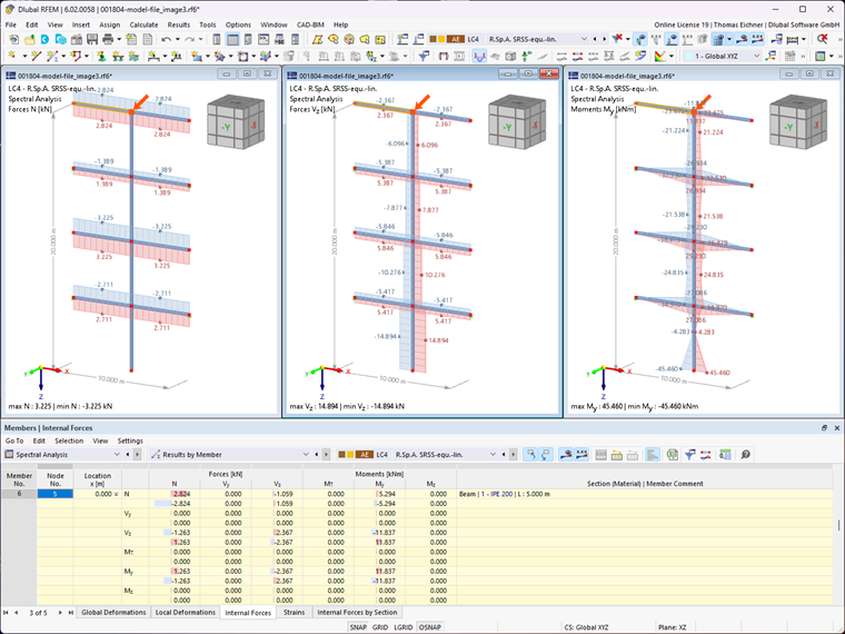
Now the internal forces are calculated by the modified SRSS rule. Due to the equivalent linear combination, the internal forces and moments are calculated separately for each maximum action. The following internal forces result for the maximum axial force.

Coefficients of equivalent linear combination for maximum axial force

fmaxN,LF1 = 1.361 kN2.823 kN = 0.482fmaxN,LF2 = -0.246 kN2.823 kN = -0.087fmaxN,LF3 = 0.815 kN2.823 kN = 0.289fmaxN,LF4 = -2.322 kN2.823 kN = -0.822

Maximum axial force - calculated by equivalent linear combination

NmaxN = 0.482 · 1.361 kN - 0.87 · (-0.246 kN) + 0.289 · 0.815 kN - 0.822 · (-2.322 kN) = 2.823 kN

Corresponding shear force - calculated with equivalent linear combination

Vz,maxN = 0.482 · 0.480 kN - 0.087 · (-1.635 kN) + 0.289 · (-0.556 kN) - 0.822 · 1.546 kN = -1.058 kN

Corresponding moment - calculated with equivalent linear combination

My,maxN = 0.482 · (-2.400 kNm) - 0.087 · 8.174 kNm + 0.289 · 2.781 kNm - 0.822 · (-7.732 kNm) = 5.292 kNm

Now, this procedure must be carried out for all actions. The resulting internal forces and moments are shown in the following table.

Axial Force N Shear Force Vz Moment My
Max N 2.823 kN -1.058 kN 5.292 kNm
Min N -2.823 kN 1.058 kN -5.292 kNm
Max VZ -1.263 kN 2.367 kN -11.836 kNm
Min VZ 1.263 kN -2.367 kN 11.836 kNm
Max My 1.263 kN -2.367 kN 11.836 kNm
Min My -1.263 kN 2.367 kN -11.836 kNm

The graphic in RFEM still shows only the maximum internal forces and moments. However, the differences are visible in the table.

Conclusion and Additional Applications

It was possible to show that the corresponding internal forces are preserved by using the equivalent linear combination. If this combination rule is used and imported into the design modules, you usually get more economical results. These results are then automatically included in the design add-ons.

It is also possible to use the equivalent linear combination outside of the spectral analysis. It can be activated for any result combination in its general data, provided that the SRSS rule is used. The procedure is similar for the CQC rule. However, the CQC rule can only be used for those result combinations in which only load cases of the earthquake category have been used and the parameters of the CQC rule have been defined in the load case itself.

The question that remains unanswered is, which combination rule should finally be used for the design? In any case, the CQC rule provides more accurate results, as it can take into account the relevance of mode shapes lying close to each other. The SRSS rule can be used in manual calculations. In computer-aided calculations, for example for dynamic analyses performed in RFEM 6 / RSTAB 9, we recommend using the CQC rule written as a linear combination, as this provides correct and economical results in all cases. The increased computational effort is negligible.

Author

Thomas Eichner, M.Sc.

Thomas Eichner, M.Sc.

Product Engineering & Customer Support

Mr. Eichner is responsible for the development of products for dynamic analysis and provides technical support for our customers.

Keywords

Dynamics Dynamic and Seismic Analysis Earthquake Response Spectrum Combination Modal Response Dynamic Analysis Equivalent Linear Combination RFEM 6 RSTAB 9 Technical Article

Reference

[1]   Eurocode 8: Design of structures for earthquake resistance - Part 1: General rules, seismic actions and rules for buildings; EN 1998‑1:2004/A1:2013
[2]   Katz, C.: Anmerkung zur Überlagerung von Antwortspektren. D-A-CH Mitteilungsblatt, 2009.

Links

Write Comment...

Write Comment...

  • Views 203x
  • Updated 08/10/2023

Contact Us

Contact Dlubal

Do you have further questions or need advice? Contact us via phone, email, chat, or forum, or search the FAQ page, available 24/7.

(267) 702-2815

[email protected]

Integrated Rhino/Grasshopper Workflows in RFEM 6 (USA)

Integrated Rhino/Grasshopper Workflows in RFEM 6 (USA)

Webinar 09/28/2023 2:00 PM - 3:00 PM EDT

Masonry Wall Design in RFEM 6

Masonry Wall Design in RFEM 6

Webinar 10/06/2023 10:00 AM - 11:00 AM CEST

Introduction to RFEM 6 Interface with Grasshopper

Introduction to RFEM 6 Interface with Grasshopper

Webinar 10/12/2023 2:00 PM - 3:00 PM CEST

Buckling Analysis in RFEM 6

Buckling Analysis in RFEM 6

Webinar 09/21/2023 2:00 PM - 3:00 PM CEST

Design of Massive RSECTION Sections in RFEM 6

Webinar 09/14/2023 2:00 PM - 3:00 PM CEST

Online Training | English

RFEM 6 | Dynamic Analysis and Seismic Design According to EC 8

Online Training 09/14/2023 8:30 AM - 12:30 PM CEST

Automated Workflow with JavaScript in RFEM 6

Automated Workflow with JavaScript in RFEM 6

Webinar 09/05/2023 2:00 PM - 3:00 PM CEST

Online Training | English

Eurocode 5 | Timber Structures According to DIN EN 1995-1-1

Online Training 08/31/2023 8:30 AM - 12:30 PM CEST

NBC 2020 Response Spectrum Analysis in RFEM 6

NBC 2020 Response Spectrum Analysis in RFEM 6 (USA)

Webinar 08/29/2023 2:00 PM - 3:00 PM EDT

RFEM 6
Hall with Arched Roof

Main Program

The structural analysis program RFEM 6 is the basis of a modular software system. The main program RFEM 6 is used to define structures, materials, and loads of planar and spatial structural systems consisting of plates, walls, shells, and members. The program can also design combined structures as well as solid and contact elements.

Price of First License
4,450.00 EUR
RSTAB 9
Structural Frame and Truss Analysis Software

Main Program

The structural frame & truss analysis and design program RSTAB 9 contains a similar range of functions as the FEA software RFEM, paying special attention to frames and trusses. Therefore, it is very easy to use and for many years, it has been the best choice for the structural analysis of beam structures consisting of steel, concrete, timber, aluminum, and other materials.

Price of First License
2,850.00 EUR