


The selection of nodes and members is described in Chapter 2.2 and Chapter 9.2.

In the Parameters section, you can check the boundary conditions of the connected structural components. You can also adjust the Construction Status, if necessary. The current member is highlighted in color in the graphic window.
The Angles of the members are based on the geometric conditions of the model defined in RFEM or RSTAB.
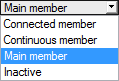
If more than two members are connected to a node, the following definition options are available for the Construction Status of the members:
- Main member – Controls all other members as well as the cutting and its priority
- Continuous member – Only available for the With continuous member joint type
- Connected member
- Inactive – Excludes the member from the design
Note
When defining main and connecting members, it is necessary to observe certain geometric conditions:
- A maximum of one member can be connected.
- For the minimum length of the connected member, the condition applies that the screwed-in screw must not protrude from the member.
- There must be a minimum angle of 30° between the members in the xy plane. In the xz plane, any angle is possible. This also allows for so-called shift cuts between members.
- For the Main member joint type, the cuts are limited to angles between 75° and 105°.
- For the Front to front joint type, the angle of the connected member must not exceed 60°.
Note
With the status Main member for all members, you can connect more than one member to the node, like in the Timber - Steel to Timber module (see Figure 9.19).
This is advantageous if you only want to design the connection in a complex joint geometry.
For the joint type Main member, you can freely select the inclination, cutting, and eccentricity within the described limits.