You can also examine the design results graphically on the model, which gives you a better insight into the conditions of each member. Make sure that the 'Wireframe Model' option is still active. If necessary, you can set it via the
![]() button on the toolbar.
button on the toolbar.
In the Navigator - Results (
![]() tab), the steel design results are arranged in two main categories:
tab), the steel design results are arranged in two main categories:
- Design Checks
- Additional Results
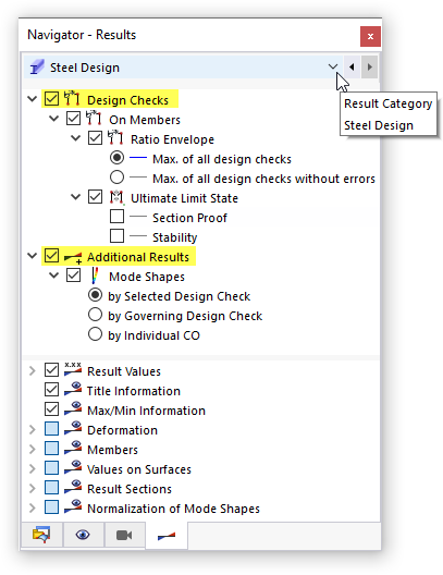
The 'Design Checks' items include the section proof and stability design results, while the 'Additional Results' manage the mode shapes.
If static analysis results are shown, set the steel design results by either clicking the
![]() button on the table toolbar or selecting the Steel Design category in the navigator.
button on the table toolbar or selecting the Steel Design category in the navigator.
Design Checks
Only the 'Ultimate Limit State' results are available since the SLS and fire resistance designs were excluded (see the Deactivating Design of 'Serviceability' and 'Fire Resistance' image).
Section Proof
Clear the Ratio Envelope check box for a specific inspection of the results (1). Then select the Section Proof check box to exclusively display that type of results (2).
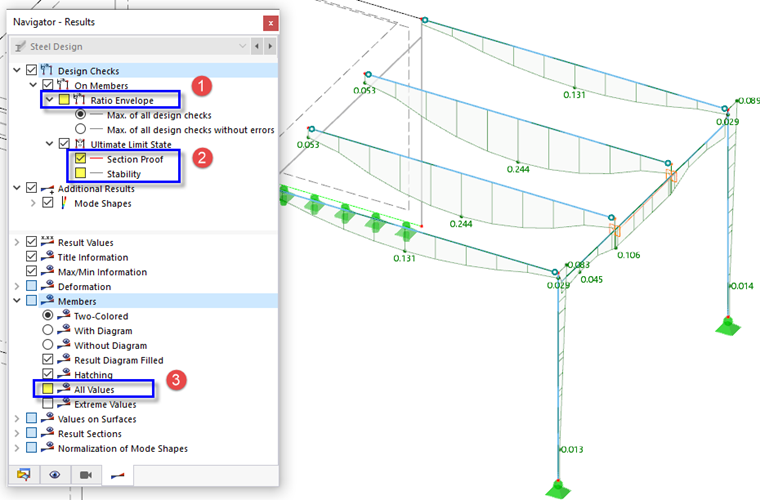
If the All Values check box of the 'Members' tree item in the bottom section is cleared (3), only the maximum values of each member are shown.
Stability
Clear the Section Proof check box and select the Stability check box instead. The maximum ratios of the stability design are displayed along the members.
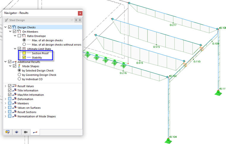
As shown in the graphics, the two internal platform girders have the highest ratios of all steel members.
Mode Shapes
Mode shapes can be displayed for single members related to a specific design check or for all members related on the governing checks. Every mode shape is based on a unique sub-model whose boundary conditions are defined by the member-specific effective lengths and supports (see the Displaying Effective Lengths with Nodal Supports image) and the loading.
To display the mode shape of an inner platform girder, proceed as follows:
- Set the Design Ratios on Members category in the table toolbar (1).
- Select the Design Ratios by Member table (2).
- Select the Stability results of member no. 8 by clicking the last line (3).
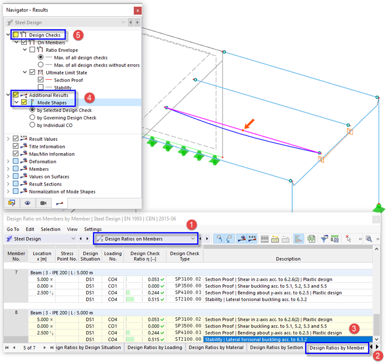
- In the navigator, select the Mode Shapes in the 'Additional Results' tree (4). The mode shape associated with lateral torsional buckling is represented by a line at the platform girder.
- Switch off the design ratios by clearing the Design Checks check box to display only the mode shape (5).
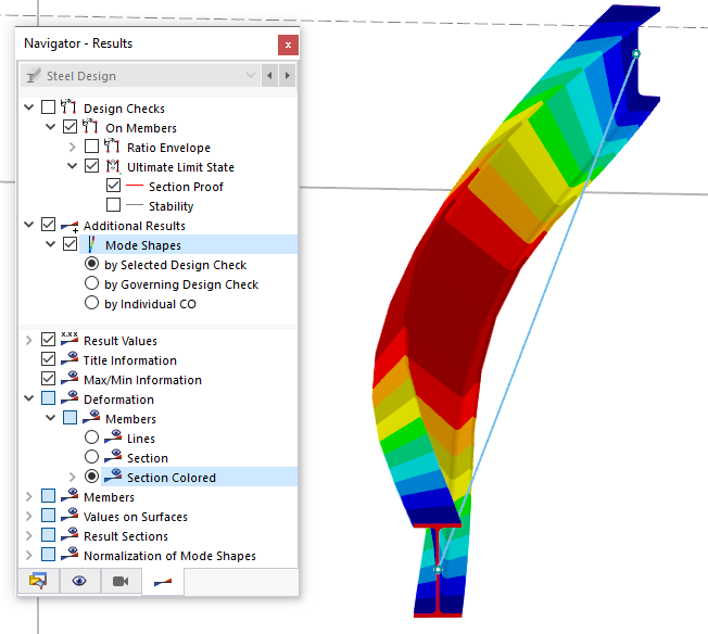
The line represents a rudimentary view of the mode shape. Select the Section Colored option in the 'Deformation' tree item located at the bottom part of the navigator. You can then inspect the lateral torsional buckling of the girder section in a realistic view.