


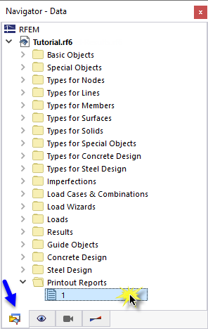
The steel design data can be added to the printout report that was created in Part 1. To open this document, double-click the 1 item in the Printout Reports category of the 'Navigator - Data'.
In the printout report, open the 'Printout Report Manager' by clicking the
![]() button on the toolbar (second from the right). Alternatively, select Edit Printout Report on the Edit menu.
button on the toolbar (second from the right). Alternatively, select Edit Printout Report on the Edit menu.
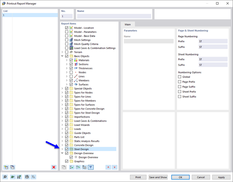
Activate the Steel Design report item folder to include the design data. Then click Save and Show.
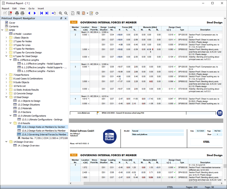
Chapter 13 of the printout report contains the default data of the steel design.
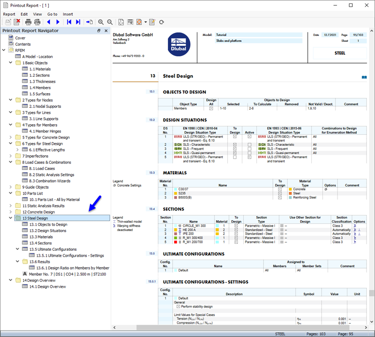
Chapter 13.6.1 contains the design ratios of each member.
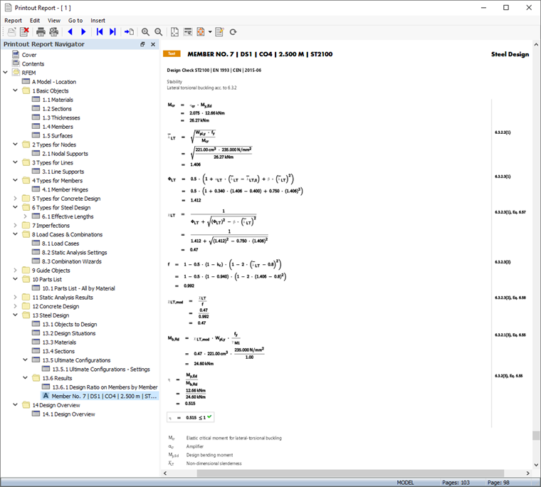
The design details that you have printed in the table (see the Design Check Details image) are placed at the end of Chapter 13. If you want, you can drag that item to another location, for example to Chapter 13.6.1.
Adjusting the Contents
To add or remove a chapter, you can use the 'Printout Report Manager' as described in Part 1. Right-click the 13.6 Results chapter, for example (1), to open the shortcut menu of this chapter. There select the Edit option (2).
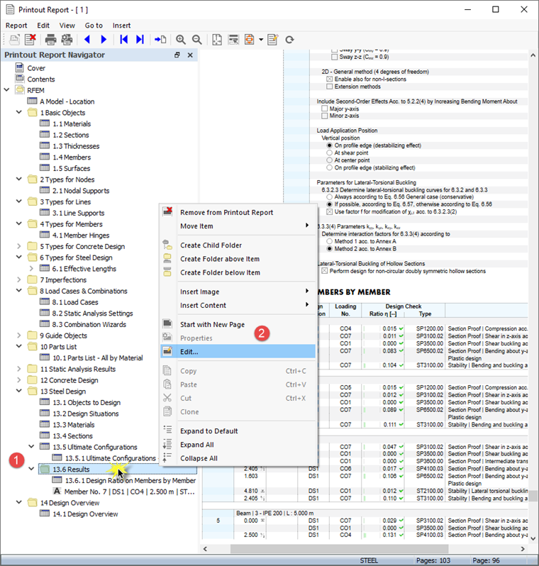
In the 'Printout Report Manager', the 'Results' category of the steel design is set in the 'Report Items' area. Activate the Design Ratio on Members by Section and Governing Internal Forces by Member check boxes, for example, to add those results to the printout report.
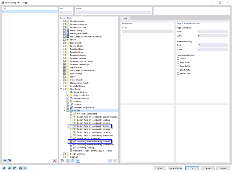
Click Save and Show to close the 'Printout Report Manager' and update the printout report.
Printing Graphics
To add an image to the printout report, minimize the preview window by clicking the
![]() button on the 'Printout Report' title bar. The RFEM workspace reappears showing the mode shape of the platform girder (see the
Mode Shape in Section View
image). Rotate and zoom the model for a good view of the mode shape.
button on the 'Printout Report' title bar. The RFEM workspace reappears showing the mode shape of the platform girder (see the
Mode Shape in Section View
image). Rotate and zoom the model for a good view of the mode shape.
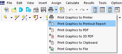
To print this image, click the
![]() button next to the
button next to the
![]() button on the toolbar. A list of printing options is opened. Click Print Graphics to Printout Report.
button on the toolbar. A list of printing options is opened. Click Print Graphics to Printout Report.
The preview of the image is presented with some options to adjust the layout.
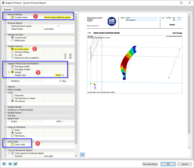
Select the Custom Name check box in the 'Picture Settings' area (1). Then enter Mode shape platform girder in the text box to the right to replace the default title. Make sure that As screen view is set in the 'Graphic Pictures' area (2).
In the 'Graphic Picture Size and Rotation' area, select the Height option so that you can define the vertical size of the image (3). Enter the Height Ratio of 50%, which means that only half of the page is used. To hide the panel, clear the Color scale check box in the 'Color Scale' area (4). Then click Save and Show.
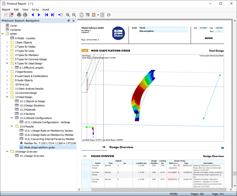
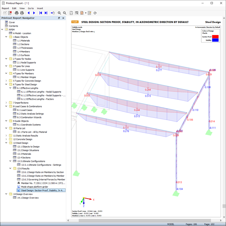
The printout report is created again with the image on the last page of the 'Steel Design' chapter.
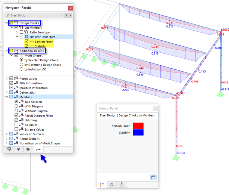
Minimize the printout report again. In the RFEM workspace, select the 'Navigator - Results'. Display the diagrams of the two ULS design checks by selecting the Design Checks check box and activating the Section Proof and Stability items. Clear the Additional Results check box to switch off the mode shapes.
To print the design checks image, click the
![]() toolbar button again (see the Options 'Print Graphics' image). The preview appears for you to adjust the layout.
toolbar button again (see the Options 'Print Graphics' image). The preview appears for you to adjust the layout.
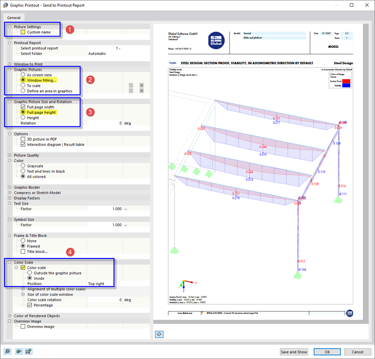
Clear the Custom Name check box in the 'Picture Settings' area to apply the default title (1). In the 'Graphic Pictures' area, select the Window filling option (2).
To use the entire page for the image, select Full page height (3). Activate the Color scale check box to display the panel with the legend (4). Then click Save and Show so that you can check the image in the printout report.
Finally, close the printout report by clicking the
![]() button.
button.
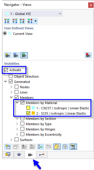
You have now completed the steel design part of the tutorial. Clear the Activate check box of the 'Visibilities' (see the Activating Visibility of Steel Members Only image) so that all objects are displayed again.
Save the data by clicking the
![]() button on the toolbar.
button on the toolbar.