


The frame girder is not only supported at its ends, but also by the two inner platform girders. They represent lateral supports reducing its effective length. Due to the eccentricity of the frame girder, it is necessary to adjust the node types of those platform girders so that they can be adequately taken into account by the software.
Node Types
Select two end nodes of central platform girders (nos. 23 and 21) by drawing a window over them. Then right-click one of those nodes to open the shortcut menu.
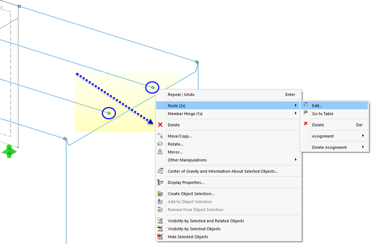
Select Node (2x) and Edit to open the "Edit Nodes" dialog box. In the "Categories" area, select the On Line node type option from the list.
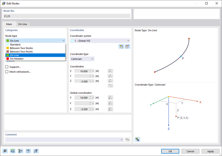
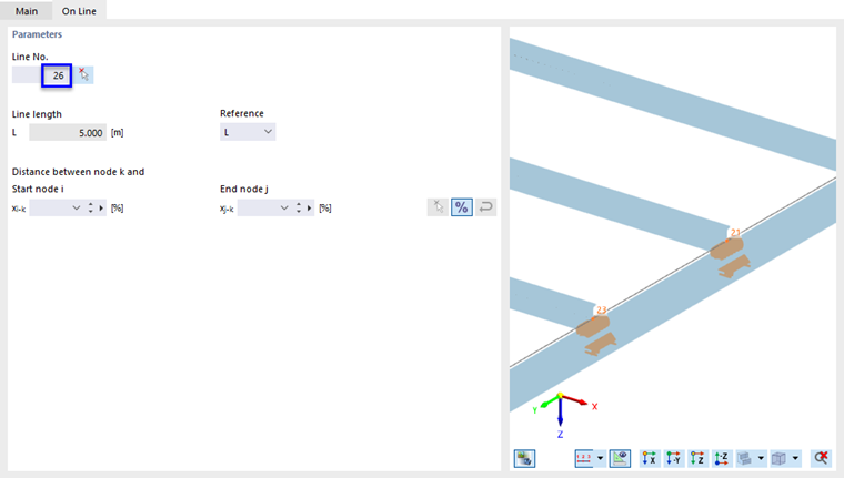
The "On Line" tab opens. Make sure that line 26 is allocated – it is the definition line of the frame girder.
Click OK so that the line is allocated to the nodes of the two platform girders. Then click Yes to confirm the question as to whether the results are to be deleted.
Effective Lengths
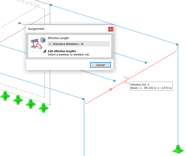
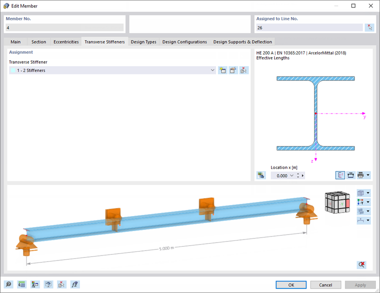
Double-click the frame girder (member no. 4) to define its design settings.
In the "Edit Member" dialog box, select the Design Types tab. As the frame girder is laterally supported by the connecting platform girders, a new type of effective lengths is required again.
Click the
![]() button as seen in the
Creating New Type of Effective Length
image to open the "New Effective Lengths" dialog box.
button as seen in the
Creating New Type of Effective Length
image to open the "New Effective Lengths" dialog box.
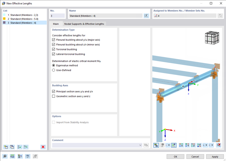
The default settings are appropriate. Select the Nodal Supports & Effective Lengths tab.
The start and end nodes are supported with the default settings. To add the supports of the two connecting platform girders along the beam, select the Intermediate nodes check box (1).
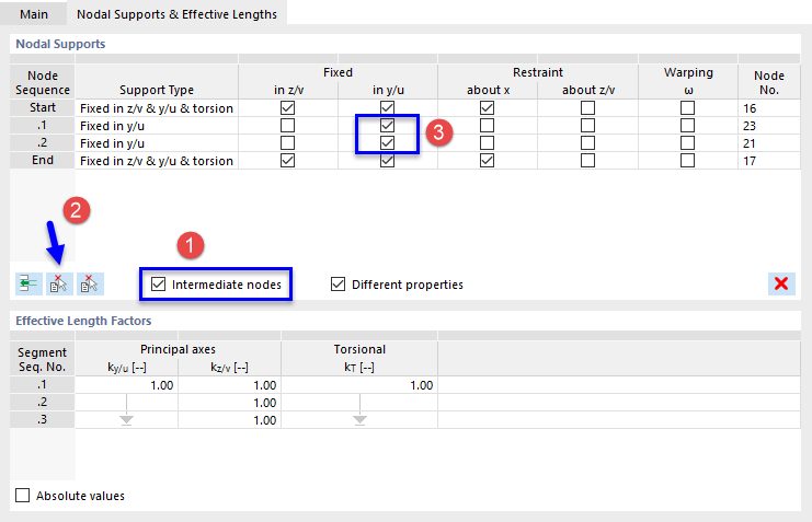
Click the left
![]() button to define the template member having intermediate nodes (2). Then select the frame girder (member no. 4) by clicking it in the workspace.
button to define the template member having intermediate nodes (2). Then select the frame girder (member no. 4) by clicking it in the workspace.
Two lines are inserted in the "Nodal Supports" area of the "New Effective Lengths" dialog box (see the Adding Intermediate Supports image). Select the Fixed in y/u check boxes for each of the intermediate nodes (3): The connecting beams represent lateral supports in the y-axis of the girder, which you can check in the real view mode (see the Defining Eccentricity image below).
The platform beams are connected at the upper flange of the frame girder. This eccentricity can be accounted for when the mode shapes are determined.
Select the line of the first intermediate support (1).
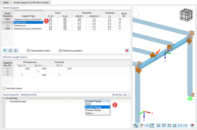
In the "Nodal Supports - Additional Data" area, open the list of eccentricity types and select At upper flange (2).
Then select the line of the second intermediate support in the "Nodal Supports" area (node sequence .2) and assign the At upper flange eccentricity as well.
Click OK to close the dialog box and return to the "Edit Members" dialog box.
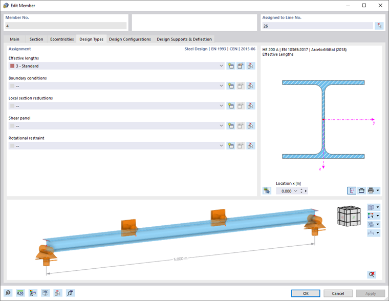
On the "Design Configurations" tab, the "Default" ultimate configuration is set for the frame girder, too.
Transverse Stiffeners
Select the Main tab. In the "Options" area, activate the Transverse Stiffeners check box.
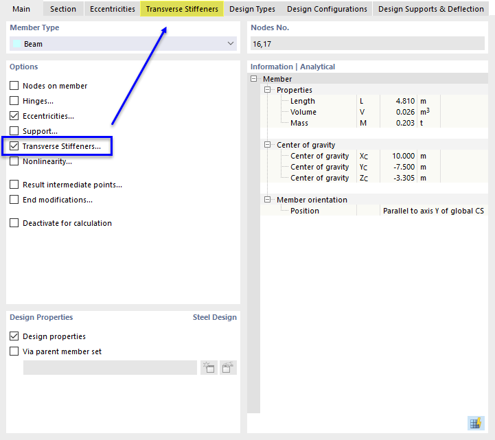
The Transverse Stiffeners tab is added where you can define the parameters. Select that tab.
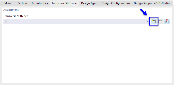
Click the
![]() button to create a new type of transverse stiffener. The "New Member Transverse Stiffener" dialog box opens.
button to create a new type of transverse stiffener. The "New Member Transverse Stiffener" dialog box opens.

In the "Stiffener Type and Location" area, select the Flat stiffener type from the list (1). It is arranged "Double-sided" automatically, which is applicable.
The location of the stiffener from the member start is to be determined with respect to the user-defined eccentricity from the center line of the column section: 1.667 m – 0.190/2 m = 1.572 m. Enter that value in the 'x [m]' column (2). (If 'x [%]' is displayed, click the
![]() button to switch to 'x [m]'.)
button to switch to 'x [m]'.)
To apply the stiffeners to the two platform girders, select the Multiple option (3).
In the 'Parameters | Flat' area, the S235 material is set by default. Two stiffeners are preset (n = 2). Enter the offset Δ between, which is 5 m / 3 = 1.667 m (4).
Lastly, enter the dimensions of the flat bars whose thickness is 8 mm (5).
The value of the "Resulting warp spring" is shown at the bottom of the dialog box.
Click OK to close the dialog box and return to the "Edit Members" dialog box.
Click OK to assign the effective lengths and stiffeners to the frame girder.
