


Set the Steel Design category in the list again. The "Not Valid / Deactivated" table is displayed. It gives an overview of the cross-sections, materials, and surfaces that were not considered during the steel design.

To check the specific design results of each member, use the categories in the toolbar list. Each category has a set of tables assigned.
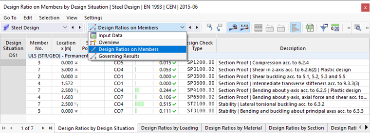
Design Ratios on Members
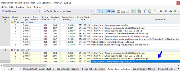
Select the Design Ratios on Members category (1). The design ratios of each member are listed by different criteria in each table sheet. Set the Design Ratios by Cross-Section table (2).
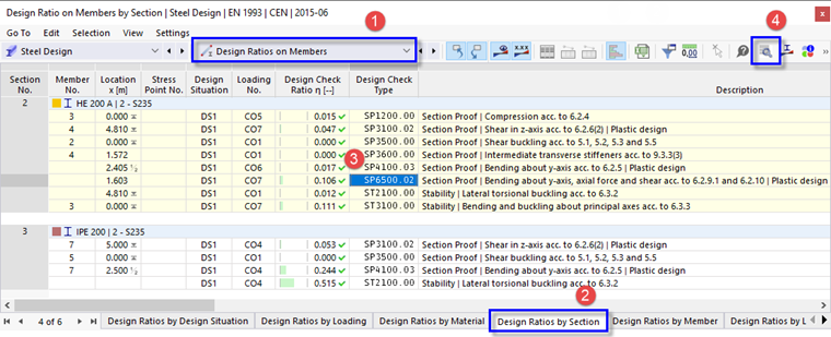
This table displays the maximum results of each cross-section. The values listed in the "Design Check Ratio" column represent the ratios of the existing design values to the respective design resistances. They include the section proofs as well as the stability checks. The former are labeled as "SP" check types, the latter as "ST". For example, "SP6500.02" represents the section proof for bending about the y-axis, axial force and shear according to EN 1993-1-1, 6.2.9.1 and 6.2.10. Select this line in the HEA 200 results (3). The highest ratio of that design type for this cross-section was calculated for the frame girder (member no. 4). The location x is marked by an arrow in the graphics.
To examine the design details of this check, click the
![]() button on the table toolbar (4). The "Design Check Details" window opens.
button on the table toolbar (4). The "Design Check Details" window opens.
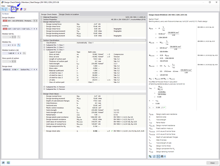
This window presents all the parameters of the design and the relevant equations. By clicking the
![]() button in the bottom-right area, you can switch between values and symbols displayed in the formulas of the design.
button in the bottom-right area, you can switch between values and symbols displayed in the formulas of the design.
When you open the "Section Classification" tree item, you can also check the classification of the HEA section.
To show the results diagram of the cross-section, click the
![]() button on the toolbar.
button on the toolbar.
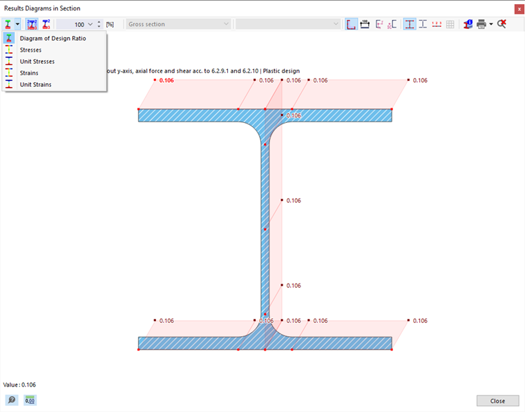
Using the
![]() list button, you can also display the stresses or strains of the frame girder cross-section. Click Close to quit this window.
list button, you can also display the stresses or strains of the frame girder cross-section. Click Close to quit this window.
To check the shear buckling design results of this member, select the SP3500 option from the "Design check" list.
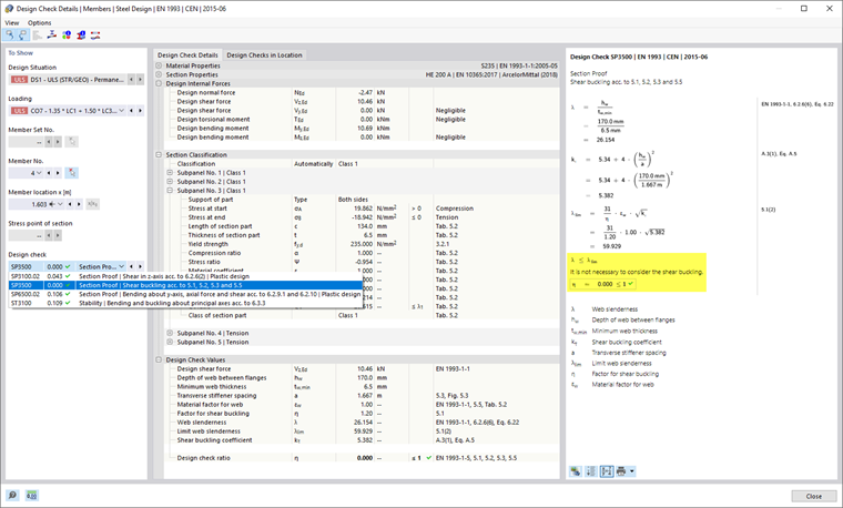
Since the web slenderness of the HEA cross-section is below the limit value, it is not necessary to consider shear buckling. The transverse stiffeners that were defined for the frame girder thus have no influence on this type of design.
Return to the tables by clicking Close.
The highest overall ratio of the stability design is for the IPE 200 cross-section. Select this line.
Click the
![]() button on the table toolbar to open the "Design Check Details" window again.
button on the table toolbar to open the "Design Check Details" window again.
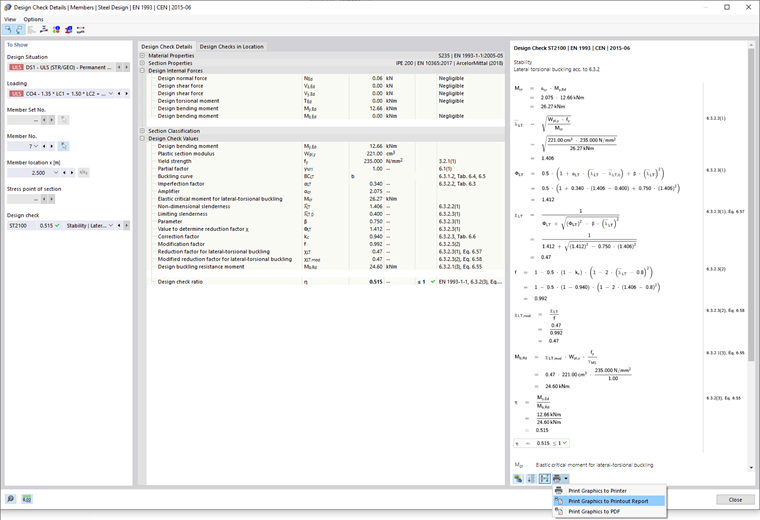
You can examine the design check values again, such as the elastic critical moment, slenderness etc.
To print the details, click the
![]() button next to the
button next to the
![]() button. Select the Print Graphics to Printout Report option. The equations of this design check are exported to the report without opening it.
button. Select the Print Graphics to Printout Report option. The equations of this design check are exported to the report without opening it.
Return to the tables by clicking Close.
Governing Results
On the table toolbar, select the Governing Results category (see the Categories for Design Results image). The internal forces and governing loading of each member are listed in several tables. The Internal Forces by Member table is preset.
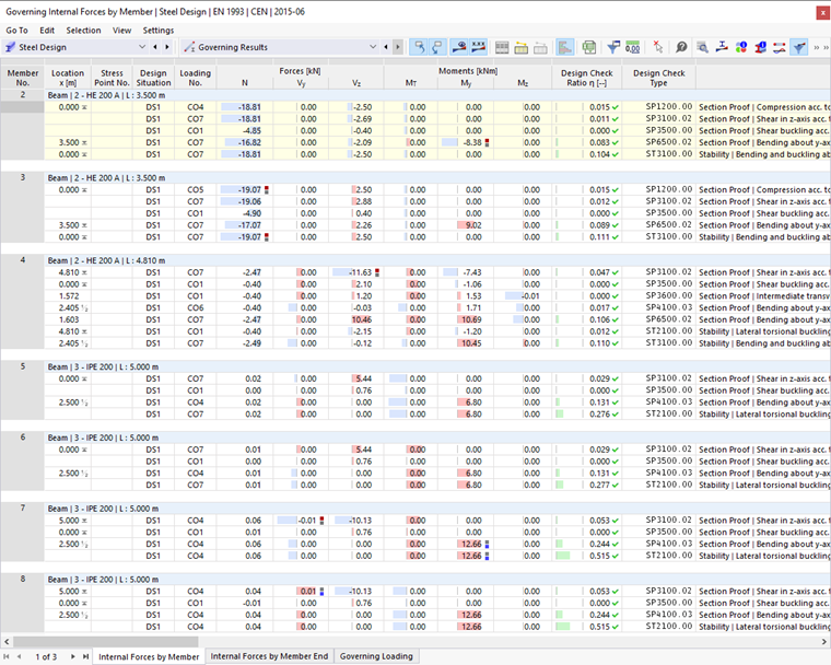
In this table, the internal forces relevant to the different types design are listed for every member. The governing forces or moments are labelled are labeled by
![]() symbols. You can also examine which load combination yields the internal forces that are relevant to each design type.
symbols. You can also examine which load combination yields the internal forces that are relevant to each design type.