


Defining Line Hinges
Line hinges are available under the Types for Lines in the Data navigator. Create a new line hinge and activate the degrees of freedom that are to be blocked; for example, the displacement in the x-direction. Use
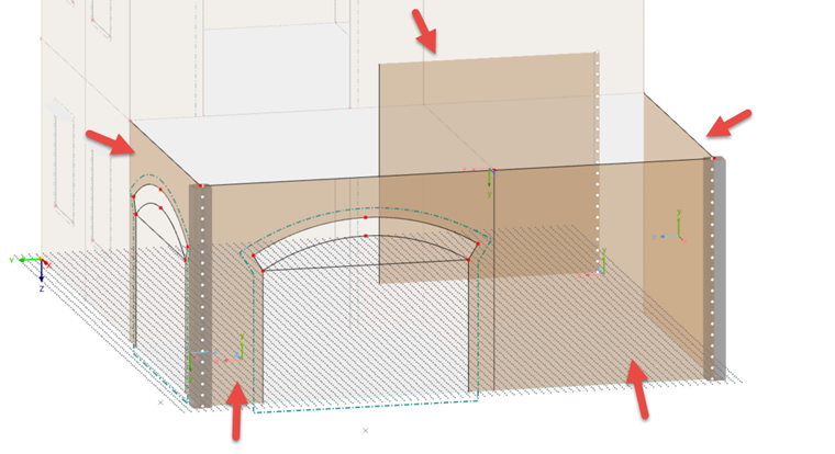
![]() to return to the graphic. By clicking it, you can first select a surface, then a line, between which the joint is to be inserted. Then, select the next surface and line. As soon as you have finished entering the data, right-click to finish your entries. In the example of the building, a line hinge was arranged between the walls and the concrete columns as well as towards the interior wall.
to return to the graphic. By clicking it, you can first select a surface, then a line, between which the joint is to be inserted. Then, select the next surface and line. As soon as you have finished entering the data, right-click to finish your entries. In the example of the building, a line hinge was arranged between the walls and the concrete columns as well as towards the interior wall.

Defining Surface Supports
The floor slab requires a support that can be activated in the editing dialog box. In the associated tab, you can select an already defined surface support or create a new surface support. As in the case of line hinges, there is a separate dialog box where you can define the support conditions.


Slab-Wall Connections
The connections between the floors and the walls can also be modeled in RFEM 6 using line hinges. To do this, open the editing dialog box by double-clicking the slab and activate the hinges under Options. An additional tab appears where you can select the line hinge. In the selection options, there is also the option to create a new line hinge. Choose this option and activate the "slab-wall connections".

In the tab of the same name, you can enter an offset and a block width, if necessary. Then, select a ceiling slab in the graphic first, and then all the lines on which a slab-wall connection is to be created. After selecting all slabs with their delimiting lines, you can click "OK" to confirm and use the
![]() button to generate all the line hinges required. If you get an error message, do not worry. The error message arises from the fact that no connection is created between the concrete slab and the concrete parapet of the roof surface.
button to generate all the line hinges required. If you get an error message, do not worry. The error message arises from the fact that no connection is created between the concrete slab and the concrete parapet of the roof surface.

If you go to a generated line hinge in the list of line hinges, you will find the "φx - Force/Moment Diagram" tab. It shows graphically which moments from the ceiling slab can be transferred by the joint at a certain axial force in the upwardly adjoining masonry wall.

The modeling is complete now, and you can continue with the load application and the calculation.