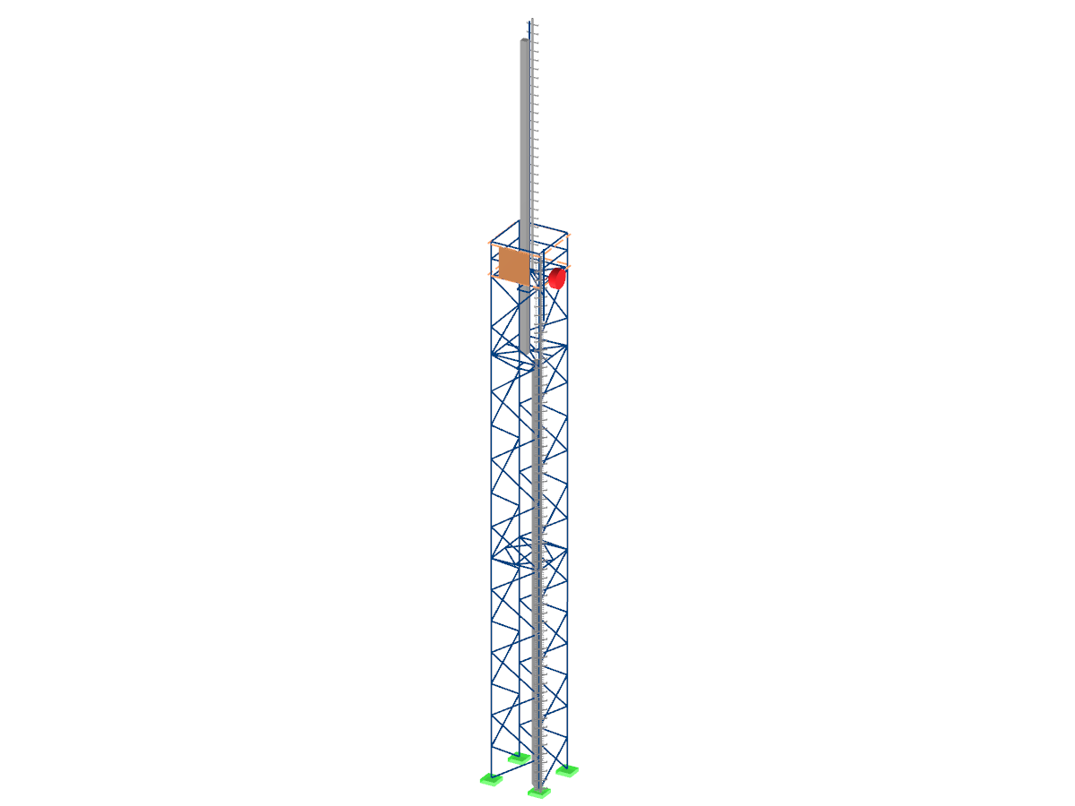
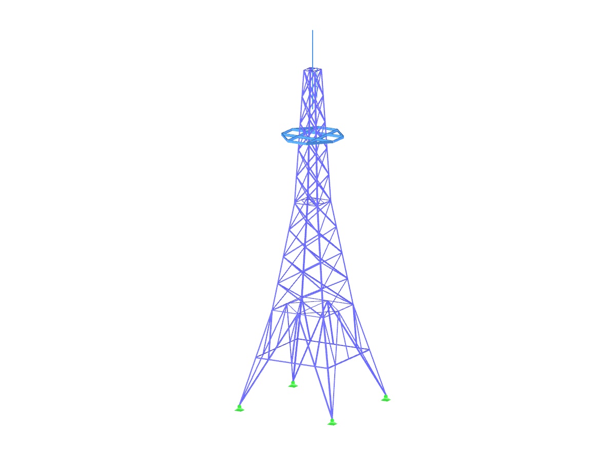
Model Used In
- Online Training | Eurocode 3 | Steel Design According to PN-EN 1993-1-1
- Eurocode 3 | Steel Structures According to DIN EN 1993-1-1
- RFEM | Normative Steel Design with Eurocode 3
- Eurocode 3 | Steel structures according to DIN EN 1993-1-1
- Eurocode 3 | Steel Structures According to DIN EN 1993-1-1
- Eurocode 3 | Steel structures according to DIN EN 1993-1-1
- Eurocode 3 | Steel Structures According to DIN EN 1993-1-1
- Eurocode 3 | Steel Structures According to EN 1993-1-1
- Eurocode 3 | Steel Structures According to DIN EN 1993-1-1
- Eurocode 3 | Steel Structures According to EN 1993-1-1
- Free Eurocode 3 training | Steel design according to PN-EN 1993-1-1
- Eurocode 3 | Steel Structures According to EN 1993-1-1
- Eurocode 3 | Steel Structures According to DIN EN 1993-1-1
- Eurocode 3 | Steel Structures According to EN 1993-1-1
Power Pole
Number of Nodes | 374 |
Number of Lines | 830 |
Number of Members | 830 |
Number of Load Cases | 31 |
Number of Load Combinations | 271 |
Number of Result Combinations | 1 |
Total Weight | 5.666 tons |
Dimensions | 47.7 x 47.7 x 96.02 feet |
Program Version | 5.15.01 |
You can download this structural model to use it for training purposes or for your projects. However, we do not assume any guarantee or liability for the accuracy or completeness of the model.
Related Models
This article describes how to create a user-defined antenna bracket to be used in RF-/TOWER Equipment.
The following technical article describes the creation of a user-defined platform for use on a four-sided tower in the RF-/TOWER add-on modules. First, start with an empty model of the 3D type and define four nodes. The numbering and position of these nodes are very important here.
Numerous nonlinearities can occur in a structural system. The RF-DYNAM Pro - Nonlinear Time History add-on module was developed in order to model them realistically in a dynamic analysis. To explain how the add-on module works, the procedure is described below with an example.
The three types of moment frames (Ordinary, Intermediate, Special) are available in the Steel Design add-on of RFEM 6. The seismic design result according to AISC 341-22 is categorized into two sections: member requirements and connection requirements.
- Wide range of joint types, for example:
- Bolted connection of diagonals without gusset plate 2D
- Bolted connection of diagonals without gusset plate 3D
- Bolted column joint
- T-, K-, and KT-joints considered for connections of diagonals
- Various categories of connections:
- A - shear/hole bearing connection
- B - slip-resistant connection at serviceability limit state
- C - slip-resistant connection at ultimate limit state
- Bolt strength classes of 4.6 - 10.9
- Bolt diameters M12 - M42
- Modifiable bolt spacing
- Visualization of the entire connection in the view window
- Consideration of the self-weight of a tower, including equipment
- Wind load distribution to exposed and shaded tower faces, or user-defined distribution
- Determination of wind loads applied to tower and equipment, especially for structures prone to vibration (gust factor)
- Assignment of surface and concentrated loads to platforms
- Optional reduction of total wind load on selected objects
- Determination of ice loads for icing classes G and R with preset ice thickness and ice flag lengths of frost
- Generation of variable load cases with surface and maintenance loads
- Generation of inside and outside platforms using the library, including parameterized models
- Tubular extension and antenna bracket libraries as 2D and 3D structures
- Antenna groups sorted by mobile network operator
- Antenna library including parabolic, lense, shell, compact, and cuboidal antennas
- Parameterized input of inner and cable ducts as well as ladders with interactive graphics
In the "Edit Section" dialog box, you can display the buckling shapes of the Finite Strip Method (FSM) as a 3D graphic.
Recommended Products for You