
In this example, the shear at the interface between concrete cast at different times and the corresponding reinforcement are determined according to DIN EN 1992-1-1. The obtained results with RFEM 6 will be compared to the hand calculation below.

A reinforced concrete beam is designed as a two-span beam with a cantilever. The cross-section varies along the length of the cantilever (tapered cross-section). The internal forces, the required longitudinal and shear reinforcement for the ultimate limit state are calculated.

The model is based on the example 4 of [1]: Point-supported slab.
The flat slab of an office building with crack-sensitive lightweight walls is to be designed. Inner, border and corner panels are to be investigated. The columns and the flat slab are monolithically joined. The edge and corner columns are placed flush with the edge of the slab. The axes of the columns form a square grid. It is a rigid system (building stiffened with shear walls).
The office building has 5 floors with a floor height of 3.000 m. The environmental conditions to be assumed are defined as "closed interior spaces". There are predominantly static actions.
The focus of this example is to determine the slab moments and the required reinforcement above the columns under full load.
The model is based on the example 4 of [1]: Point-supported slab. The internal forces and the required longitudinal reinforcement can be found the in verification example 1022. In this example, punching is examined in the axis B/2.
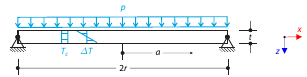
Determine the maximum deflection and maximum radial moment of a simply supported circular plate subjected to uniform pressure, uniform temperature, and differential temperature.
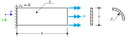
A thin plate is fixed on one side and loaded by means of distributed torque on the other side. First, the plate is modeled as a planar plate. Furthermore, the plate is modeled as one-fourth of the cylinder surface. The width of the planar model is equal to the length of one-fourth of the circumference of the curved model. The curved model thus has almost equal torsional constant to the planar model.
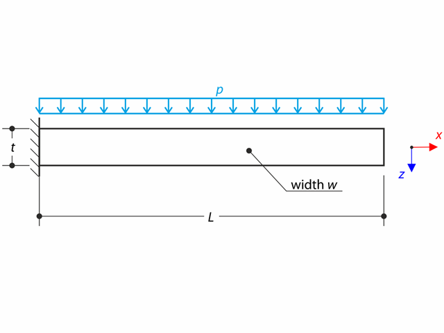
A thin plate is fully fixed on the left end and loaded by uniform pressure on the top surface.
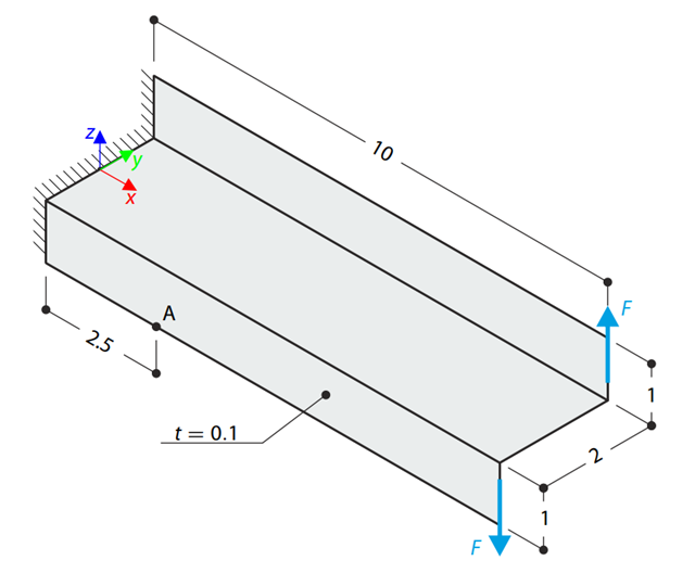
A Z-Section Cantilever is fully fixed at the end and loaded by a torque which, in the case of a shell model, is represented by a couple of shear forces. Determine the axial stress at point A (at mid-surface). The problem is defined according to The Standard NAFEMS Benchmarks.
A thin plate is fully fixed on the left end and loaded by uniform pressure on the top surface. Determine the maximum deflection. The aim of this example is to show that a surface of the surface stiffness type Without Membrane Tension behaves linearly under bending.
A membrane is stretched by means of isotropic prestress between two radii of two concentric cylinders not lying in a plane parallel to the vertical axis. Find the final minimum shape of the membrane - the helicoid - and determine the surface area of the resulting membrane. The add-on module RF-FORM-FINDING is used for this purpose. Elastic deformations are neglected both in RF-FORM-FINDING and in the analytical solution; self-weight is also neglected in this example.
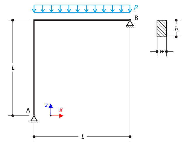
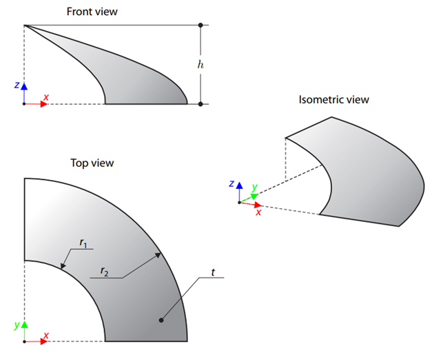
A curved beam consists of two beams with a rectangular cross-section. The horizontal beam is loaded by distributed loading. While neglecting self-weight, determine the maximum stress on the top surface of the horizontal beam.
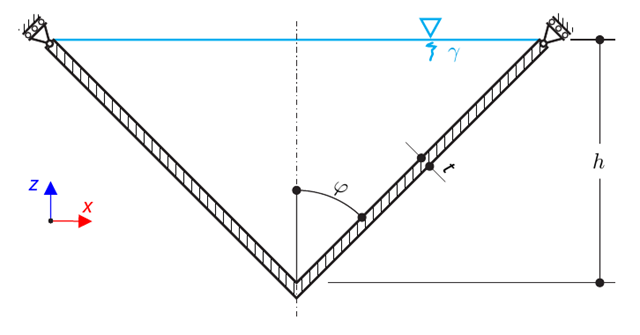
A thin-walled conical vessel is filled with water. Thus, it is loaded by hydrostatic pressure. While neglecting self-weight, determine the stresses in the surface line and circumferential direction. The analytical solution is based on the theory of thin-walled vessels. This theory was introduced in Verification Example 0084.
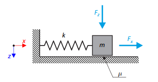
A simple oscillator consists of mass m (considered only in the x-direction) and linear spring of stiffness k. The mass is embedded on a surface with Coulomb friction and is loaded by constant-in-time axial and transverse forces.
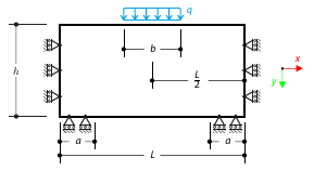
A masonry wall is exposed to a distributed load in the middle of its upper section. The Isotropic Masonry 2D material model is compared with the Isotropic Linear Elastic model, with surface stiffness property Without Tension in the nonlinear calculation.
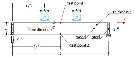
A timber beam reinforced by two steel plates at the ends is loaded by pressure. The wood fibers are parallel to the upper loaded side of the beam. The plastic surface is described according to the Tsai-Wu plasticity theory.
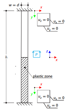
A three-dimensional block made of elastic-plastic material is fixed at both ends. The block's middle plane is subjected to a pressure load. The surface plasticity is described according to the Tsai-Wu plasticity theory.
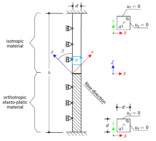
Determine the maximum deflection of a three-dimensional block fixed at both ends. The block is divided in the middle: the upper half is made of an elastic material and the lower part is made of timber - an elasto-plastic othotropic material with the yield surface described according to the Tsai-Wu plasticity theory. The block's middle plane is subjected to vertical pressure.
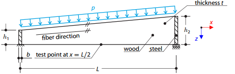
A timber beam reinforced by two steel plates at the ends is loaded by pressure. The wood fibers are parallel to the upper loaded side of the beam. The plastic surface is described according to the Tsai-Wu plasticity theory.
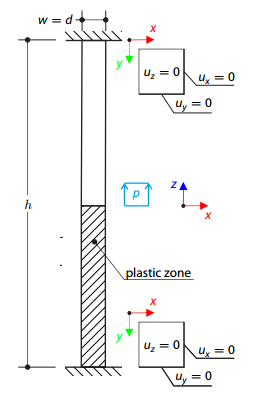
A three-dimensional block made of elastic-plastic material with hardening is fixed on both ends. The block's middle plane is subjected to a pressure load. The surface plasticity is described according to the Tsai‑Wu plasticity theory.