
A structure is consisted of an I-section beam and two tube trusses. The structure contains several imperfections and it is loaded by the force Fz. The self-weight is neglected in this example. Determine the deflections uy and uz and axial rotation φx at the endpoint (Point 4). The verification example is based on the example introduced by Gensichen and Lumpe.

Consider an ASTM A992 W 18x50 beam forspan and uniform dead and live loads as shown in Figure 1. The member is limited to a maximum nominal depth of 18 inches. The live load deflection is limited to L/360. The beam is simply supported and continuously braced. Verify the available flexural strength of the selected beam, based on LRFD and ASD.

Using AISC Manual tables, determine the available compressive and flexural strengths and whether the ASTM A992 W14x99 beam has sufficient available strength to support the axial forces and moments shown in Figure 1, obtained from a second-order analysis that includes P-𝛿 effects.
Determine the allowable axial compressive strength of a pinned 8-foot-long beam of various cross-sections made of Alloy 6061-T6 and laterally restrained to prevent buckling about its weak axis in accordance with the 2020 Aluminum Design Manual.
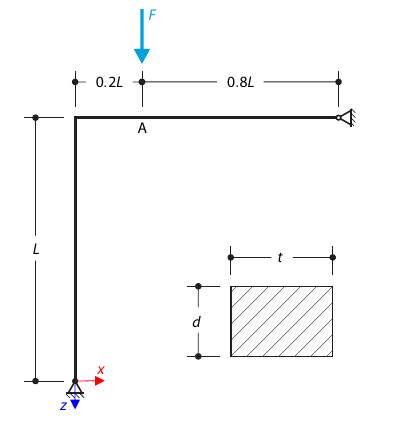
A curved frame called Lee's frame is pinned at the end points and loaded by a concentrated force at point A. Determine the deflection ratio at point A in the given load steps. The problem is defined according to The NAFEMS Non-Linear Benchmarks.
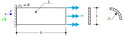
A thin plate is fixed on one side and loaded by means of distributed torque on the other side. First, the plate is modeled as a planar plate. Furthermore, the plate is modeled as one-fourth of the cylinder surface. The width of the planar model is equal to the length of one-fourth of the circumference of the curved model. The curved model thus has almost equal torsional constant to the planar model.
Determine the allowable axial compressive strength of a pinned 8-foot-long beam of various cross-sections made of Alloy 6061-T6 and laterally restrained to prevent buckling about its weak axis in accordance with the 2020 Aluminum Design Manual.
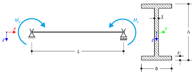
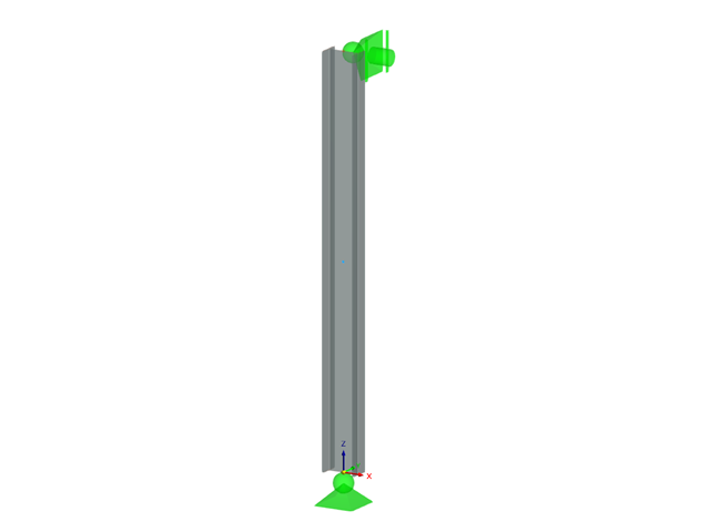
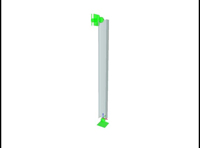
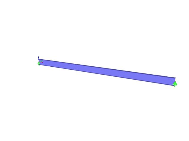
A simply supported beam is loaded by pure bending. Determine the critical load and corresponding load factor due to lateral buckling.
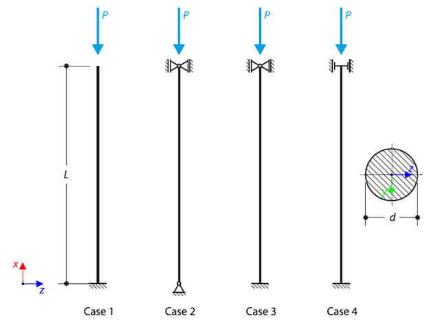
A strut with a circular cross-section is supported according to four basic cases of Euler buckling and subjected to pressure force. Determine the critical load.
Determine the allowable axial compressive strength of a pinned 8-foot-long beam of various cross-sections made of Alloy 6061-T6 and laterally restrained to prevent buckling about its weak axis in accordance with the 2015 Aluminum Design Manual.
Consider an ASTM A992 W 18×50 beam forspan and uniform dead and live loads as shown in Figure 1. The member is limited to a maximum nominal depth of 18 inches. The live load deflection is limited to L/360. The beam is simply supported and continuously braced. Verify the available flexural strength of the selected beam, based on LRFD and ASD.
Using AISC Manual tables, determine the available compressive and flexural strengths and whether the ASTM A992 W14x99 beam has sufficient available strength to support the axial forces and moments shown in Figure 1, obtained from a second-order analysis that includes P-𝛿 effects.

A column is composed of a concrete section (rectangle 100/200) and a steel section (profile I 200). It is subjected to pressure force. Determine the critical load and corresponding load factor. The theoretical solution is based on the buckling of a simple beam. In this case, two regions have to be taken into account due to different moments of inertia and material properties.
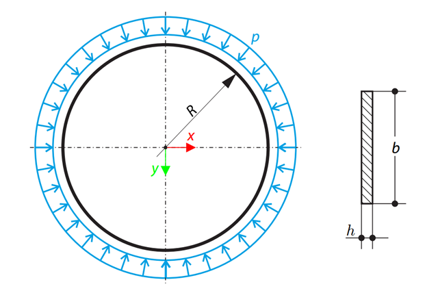
A thin circular ring of a rectangular cross-section is exposed to external pressure. Determine the critical load and corresponding load factor for in-plane buckling.
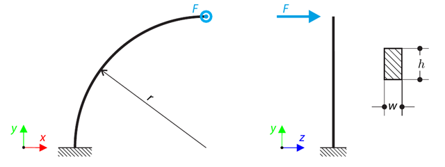
A quarter-circle beam with a rectangular cross-section is loaded by means of an out-of-plane force. This force causes a bending moment, torsional moment, and transverse force. While neglecting self-weight, determine the total deflection of the curved beam.
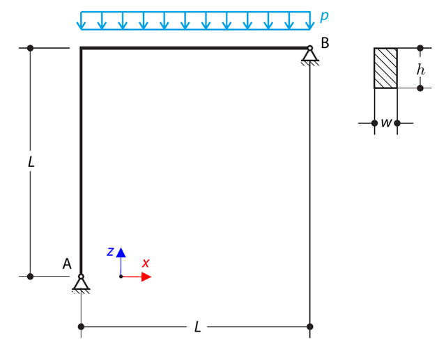
A curved beam consists of two beams with a rectangular cross-section. The horizontal beam is loaded by distributed loading. While neglecting self-weight, determine the maximum stress on the top surface of the horizontal beam.
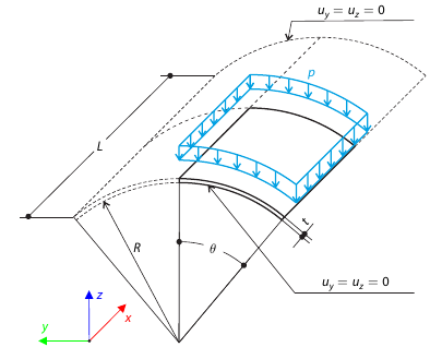
A shell roof structure under pressure load is modeled where the straight edges are free, while at the curved edges the y- and z‑translations are constrained. Neglecting self‑weight, compute the maximum (absolute) vertical deflection, and compare the results with COMSOL Multiphysics 4.3.
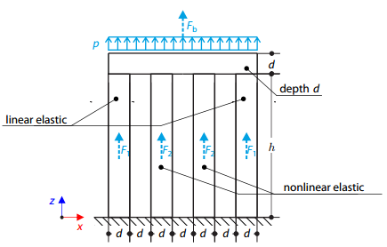
Four columns are fixed at the bottom and connected by a rigid block at the top. The block is loaded by pressure and modeled by an elastic material with a high modulus of elasticity. The outer columns are modeled by linear elastic material and the inner columns by a stress-strain diagram with decaying dependence. Assuming only the small deformation theory and neglecting the structure's self-weight, determine its maximum deflection.