Answer:
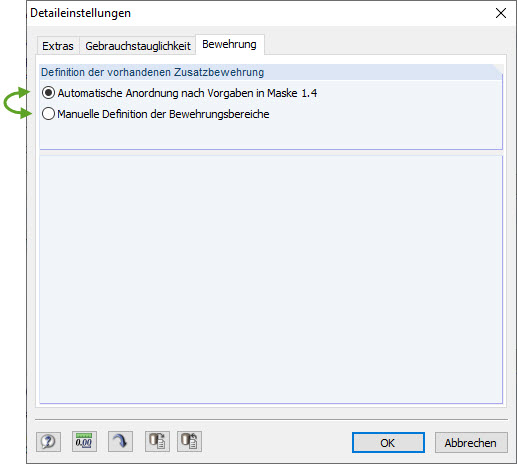
When automatically arranging the reinforcement, make sure that, in addition to the basic reinforcement, reinforcement is also applied for the serviceability limit state design checks. The default setting in the add-on module is selected in such a way that the required reinforcement from the ultimate limit state is also applied for the SLS.
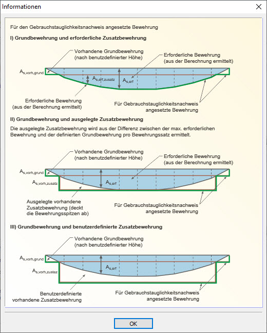
You can select the reinforcement that is applied for the SLS in "Additional Reinforcement for Serviceability State Design". The Info button explains the individual options (Image 02).
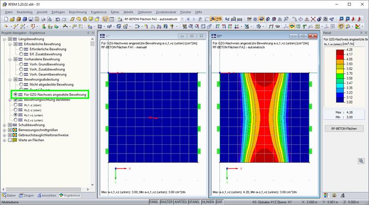
The reinforcement applied to the designs can be followed using the "Selected Reinforcement for SLS Check" function (Image 03).