FAQ 004938 EN
Why are the stresses of the 90° orientation not displayed for a layer with the orthotropy direction 90° for σb,90 in RF‑LAMINATE?
Answer
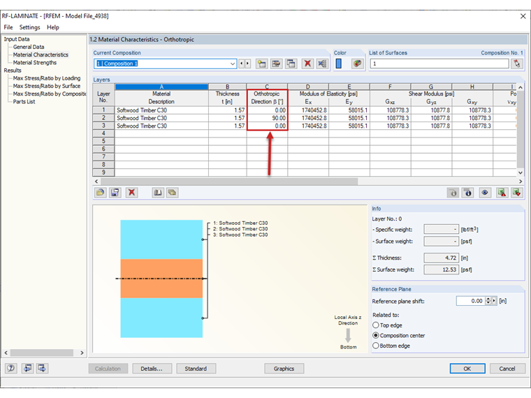
The indices of the stresses from RF‑LAMINATE, such as σb,90, do not refer to the local surface axis system from RFEM, but to the orthotropy directions defined in Window "1.2 Material Properties" in RF‑LAMINATE, see Image 01.
Image 01 - Orthotropy Directions of Layers in RF-LAMINATE
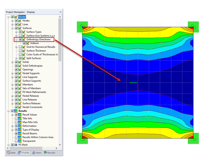
The orthotropy directions can be displayed graphically by activating them in the Display navigator, see Image 02. The red arrow represents the "zero direction" of the stress, that is, the direction of the stress σb,0.
Image 02 - Graphical Display of Orthotropy Directions
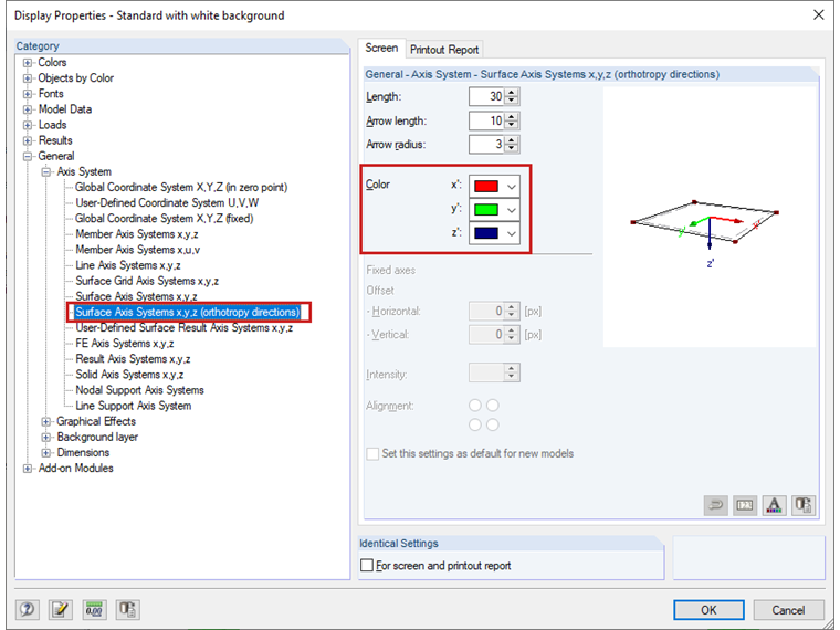
The colors of the arrows can be adjusted within the display properties (category General, Axis System, Surface Axis Systems x, y, z (orthotropy directions)), see Image 03.
Image 03 - Adjusting Colors of Axis Systems
Thus, the stress σb,0 in this direction applies to each orthotropy direction of a layer defined in RF‑LAMINATE, and σ b,90 applies to the stress transverse to the defined orthotropy directions.
Keywords
Orthotropy direction Layer Orthotropy Direction Orientation
Downloads
Contact us
Did you find your question?
If not, contact us via our free e-mail, chat, or forum support, or send us your question via the online form.
Recommended Events
Timber Beam and Surface Structures | Part 1: Modeling, Load Input, Combinatorics
Webinar 4 May 2021 2:00 PM - 3:00 PM CEST
Eurocode 5 | Timber structures according to DIN EN 1995-1-1
Online Training 20 May 2021 8:30 AM - 12:30 PM CEST
Videos
Models to Download
Knowledge Base Articles

New
Filter option for the result tables in the design modules
When designing many members in one design case, it is sometimes difficult to recognize the governing designs. To improve the overview and to display the relevant designs in a compact way, you can use the filter options under the result tables. These are included in all design modules of steel, aluminum and timber structures in RFEM and RSTAB.
Screenshots
Product Features Articles

- General stress analysis
- Graphical and numerical results of stresses and stress ratios fully integrated in RFEM
- Flexible design with different layer compositions
- High efficiency due to few entries required
- Flexibility due to detailed setting options for calculation basis and extent
- Based on the selected material model and the layers contained, a local overall stiffness matrix of the surface in RFEM is generated. The following material models are available:
- Orthotropic
- Isotropic
- User-defined
- Hybrid (for combinations of material models)
- Option to save frequently used layer structures in a database
- Determination of basic, shear and equivalent stresses
- In addition to the basic stresses, the required stresses according to DIN EN 1995-1-1 and the interaction of those stresses are available as results.
- Stress analysis for structural parts of almost any shape
- Equivalent stresses calculated according to different approaches:
- Shape modification hypothesis (von Mises)
- Maximum shear stress criterion (Tresca)
- Maximum principal stress criterion (Rankine)
- Principal strain criterion (Bach)
- Calculation of transversal shear stresses according to Mindlin, Kirchhoff, or user-defined specifications
- Serviceability limit state design by checking surface displacements
- User-defined specifications of limit deflections
- Possibility to consider layer coupling
- Detailed results of individual stress components and ratios in tables and graphics
- Results of stresses for each layer in the model
- Parts list of designed surfaces
- Possible coupling of layers entirely without shear
Frequently Asked Questions (FAQ)
- I have defined temperature loads, strain loads, or a precamber. As soon as I modify stiffnesses, the deformations are no longer plausible.
- Can the properties, such as B. the cross -section or the surface thickness as well as the material of a surface of an existing element for a new element?
- In RF-/TIMBER AWC and RF-/TIMBER CSA, I receive the error that says torsion limit exceeded. How do I bypass this error message?
- Why is the strength always reduced by the kmod value of 0.6 during the calculation in the RF‑LAMINATE add‑on module, although I have load combinations with variable loads?
- Can I consider a reduction of the stiffness according to the German regulation NCI NA.5.9 in TIMBER Pro?
- I have selected all available members for design in RF-/TIMBER Pro. Why are tapered members not designed?
- When performing the fire resistance design with TIMBER Pro, I get the error 10001. How can I fix the error?
- Is it possible to set user-defined values when viewing solid stress results?
- How can I create a curved or arched section?
- How are the signs for the release results of a line release and line hinges interpreted?
Customer Projects