Elements are connected if they share a common point.
Image 01 shows two elements. Element 1 has Point 1 and Point 2, and Element 2 has Point 2 and Point 7. Elements 1 and 2 are connected, because they share the same Point 2.
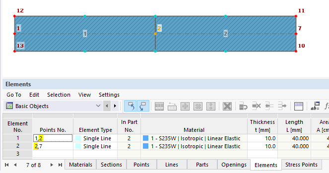
Image 02 shows two elements that cross each other. Element 1 has Point 1 and Point 2, and Element 2 has Point 7 and Point 8. Elements 1 and 2 are not connected, because they do not share the same point.
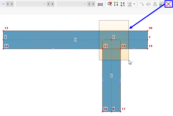
You can connect the crossing elements using the "Connect Lines and Elements" function. Simply drag a window over the area where you want to connect the elements. It is not necessary to fully capture the objects (Image 03).
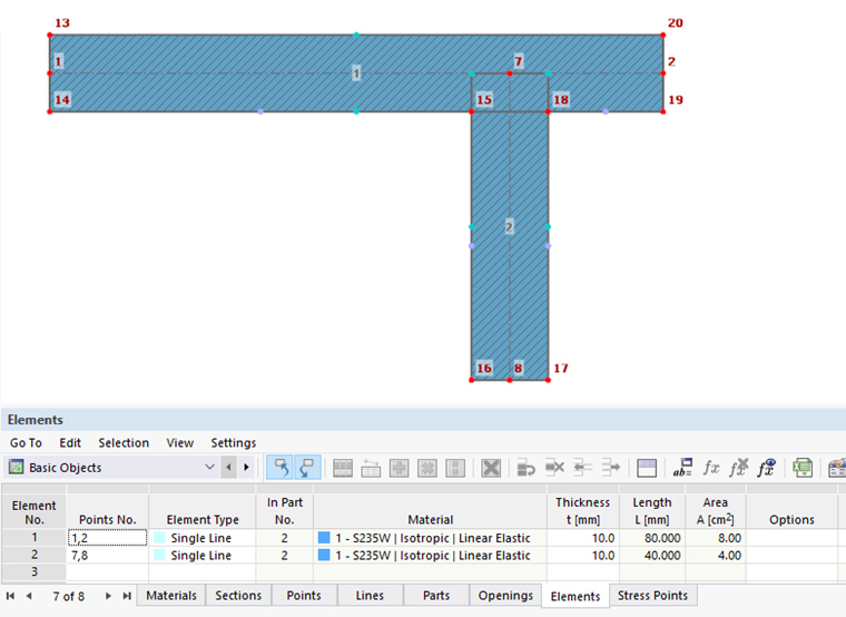
After applying the function, Element 1 is divided into Element 1 and Element 3 (Image 04). Elements 1, 2, and 3 are now connected with each other via the common Point 7.
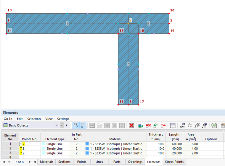
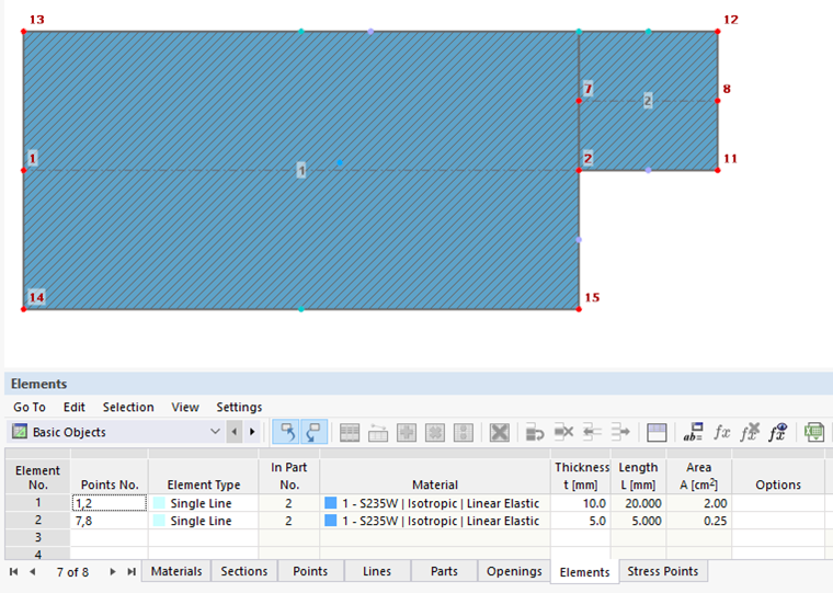
Image 05 shows two elements. Element 1 has Point 1 and Point 2, and Element 2 has Point 7 and Point 8. Elements 1 and 2 are not connected, because they do not share the same point.
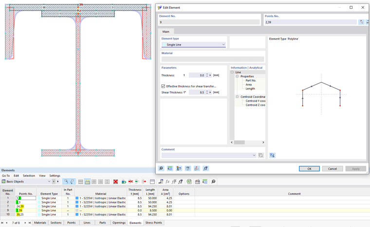
It is possible to create a connection between Point 2 and Point 7 using a null element (Element 3 in Image 06). A null element has a thickness t = 0 mm and a shear thickness t* 0 mm. Element 1 is connected to Element 3 via Point 2, and Element 3 is connected to Element 2 via Point 7, so the entire cross-section is connected.
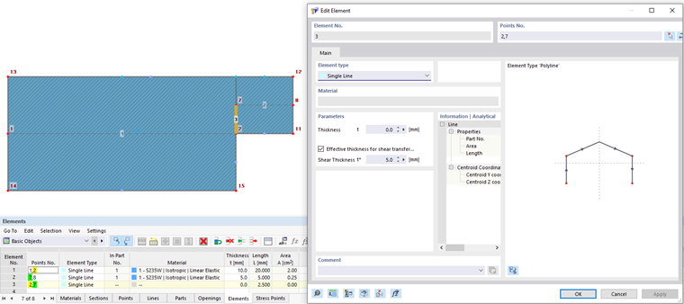
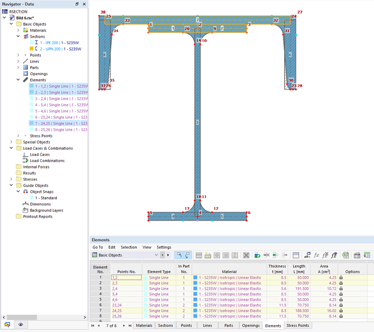
Image 07 shows two cross-sections. Cross-Section 1 is an IPE 200, containing Elements 1 through 5. Cross-Section 2 is a UPN 200 that contains Elements 6 through 8. The elements of Cross-Section 1 are not connected to the elements of Cross-Section 2, as they do not share any common points.
It is first necessary to divide the cross-sections into their individual objects (points, lines, elements, parts, openings) in order to edit them. You can do this by using the "Explode" function in the shortcut menu of the cross-sections (Image 08).

The connection of Element 7 of Cross-Section 1 with Element 1 and Element 2 of Cross-Section 2 can be created using a null element. Element 7 is to be divided at the connection point. The division is carried out automatically when setting the element, if the "Auto Connect Lines and Elements" option is activated. In Image 09, Element 7 was divided into Elements 7 and 10. Element 9 connects Element 10 and Element 7 via Point 39, and Element 1 and Element 2 via Point 2.