79 Results
View Results:
Sort by:

Cutting and Editing Plates when Modeling Steel Joints
Why is it not possible to select the plate I want to cut/edit in the Plate Editor / Plate Cut?

Different Stresses in Static Analysis and Stress-Strain Analysis
Why are the stresses of the structural analysis different from those calculated with the Stress-Strain Analysis add-on?

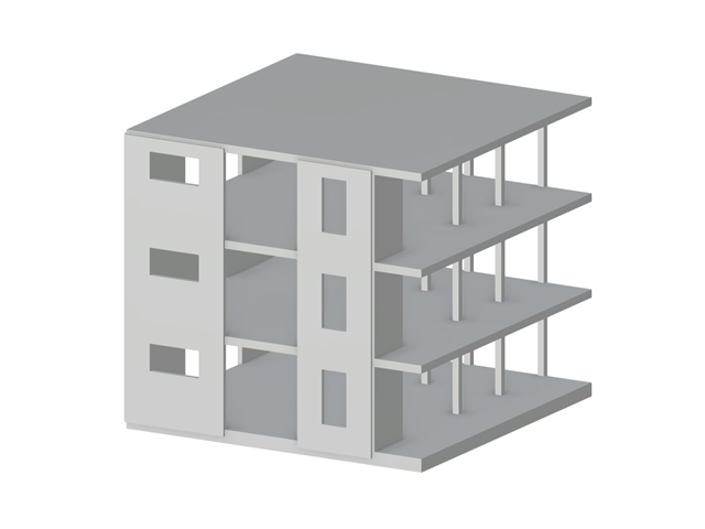
Structure Below Ground Level
Why does the integration/support of my building in the ground below the ground level not work?

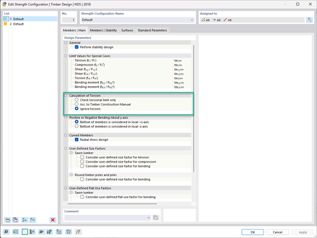
Adjusting NDS and CSA O86 Factors for Consideration in the Timber Design Add-on
How can the NDS and CSA O86 factors be manually adjusted for consideration in the Timber Design add-on?