The structural analysis software RFEM 6 is the basis of a modular software system. The main program RFEM 6 is used to define structures, materials, and loads of planar and spatial structural systems consisting of plates, walls, shells, and members. The program also allows you to create combined structures as well as to model solid and contact elements.
RSTAB 9 is a powerful analysis and design software for 3D beam, frame, or truss structure calculations, reflecting the current state of the art and helping structural engineers meet requirements in modern civil engineering.
Do you often spend too long calculating cross-sections? Dlubal Software and the RSECTION stand-alone program facilitate your work by determining section properties of various cross-sections and performing a subsequent stress analysis.
Do you always know where the wind is blowing from? From the direction of innovation, of course! With RWIND 2, you have a program at your side that uses a digital wind tunnel for the numerical simulation of wind flows. The program simulates these flows around any building geometry and determines the wind loads on the surfaces.
Are you looking for an overview of snow load zones, wind zones, and seismic zones? Then you are in the right place. Use the Geo-Zone Tool to determine quickly and efficiently snow loads, wind speeds, and seismic data according to ASCE 7‑16 and other international standards.
Would you like to try out the capabilities of the Dlubal Software programs? You have the opportunity to do so! The free 90-day full version allows you to thoroughly test all our programs.
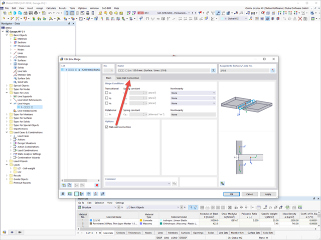
The Masonry Design add-on allows you to automatically determine the stiffness of your wall-slab hinge. The diagrams were determined as part of the research project DDmaS - "Digitizing the design of masonry structures" and are derived from the standard.
Define a line hinge on the connection line of both surfaces and activate the slab-wall connection.
You can now enter your parameters in the Slab-Wall Connection tab. Then, click the Regenerate [...] button.
The determined diagrams are displayed subsequently.
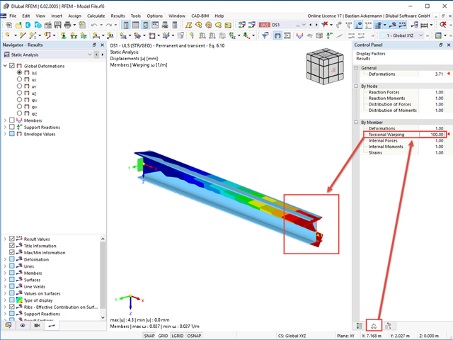
Both support forces and loads are assumed for the calculation with warping torsion in the centroid. Accordingly, an asymmetric cross-section would automatically receive torsion; see the image.
The warping of a cross-section can be displayed in the "full mode". For this, it is reasonable to increase the display factor for torsional warping in the control panel; see Image 01.
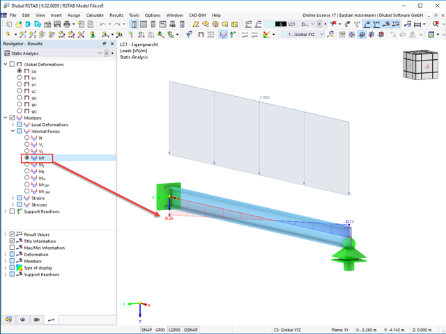
Furthermore, you can select the value of the local deformation ω [1/m] in the Results navigator; see Image 02.
RFEM and RSTAB use a variation of the subgrade reaction modulus method. The relation to stiffness modulus ES is not possible.
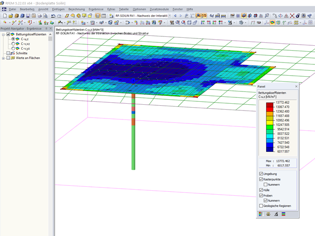
In RFEM, a multi-parameter foundation model has been implemented. This can be used to carry out a very realistic settlement calculation.
The problem, however, is to find precise values for the parameters Cu,z, Cv,xz, and Cv,yz. For this, you can use the Geotechnical Analysis add-on (for RFEM 6) or the RF-SOILIN add-on module (for RFEM 5): the subgrade parameters are calculated from the loads and the data of the geotechnical report (stiffness modulus or modulus of elasticity and Poisson's ratio, specific weights, layer thicknesses) for each individual finite element using a nonlinear method. These parameters are load-dependent and influence the behavior of the structure. The results of this iterative process are realistic settlements and internal forces in the structure.
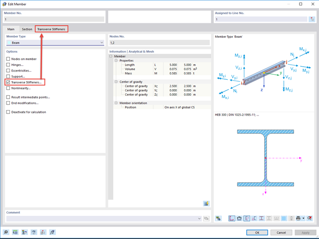
After activating Torsional Warping in the Base Data, you can define warping springs and warping restraints. For this, select the Transverse Stiffeners option in the "Edit Member" dialog box; see Image 01.
In the "Transverse Stiffener" tab, you can create several transverse member stiffeners and define the necessary parameters using the "New Transverse Member Stiffener" button. For the "End plate" stiffener type, the resulting warp spring is determined automatically; see Image 02.
In addition to other variants, you can also define a rigid warping restraint or user-defined warping spring stiffness under the "Warping restraint" stiffness type.
As an alternative, you can create member transverse stiffeners using the Data navigator or the menu bar "Insert", "Types for Members", "Member Transverse Stiffeners". In this case, you can use the select function in the "New Member Transverse Stiffness" dialog box to assign them to the corresponding members.
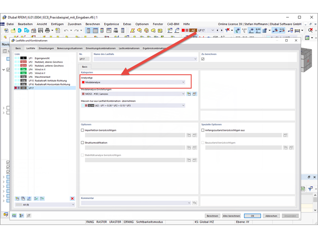
You can also define structural modifications in a load case of the Modal Analysis type. Thus, you can access the stiffness modifications of the individual objects and deactivate the selected objects, if necessary.
In order to display the mode shapes of your dynamic analysis, you have to create a load case of the Modal Analysis type and specify your settings for the modal analysis there.
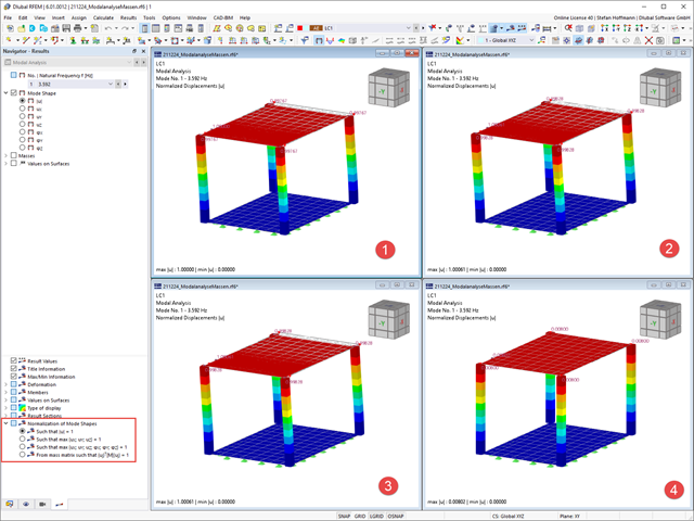
After the calculation, you can evaluate your results in the Results navigator. You can see further information in the table.
You can adjust the display of the mode shape normalization directly in the Results navigator. If the setting is changed, no recalculation is necessary.
Depending on the setting, the largest displacement or deformation represents the reference value 1, to which the other results are scaled.
Releases for warping are at each member end by default. Splitting members leads to a warping release.
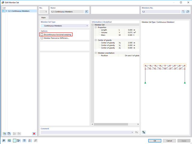
If you do not want to have a warping release there, but rather continuous warping, you need to define a member set. When activating the "Torsional Warping" add-on, the warping is transferred automatically. If this is not desired for the member set, select the "Discontinuous torsional warping" option; see the image.