Determining Required Longitudinal Reinforcement for the Shear Force
Tips & Tricks
The shear force resistance VRd,c without the calculational shear reinforcement according to, for example, Section 6.2.2 of EN 1992‑1‑1 is calculated depending on the ratio of longitudinal reinforcement. Up until now, the required longitudinal reinforcement was used from the bending analysis in the modules RF‑CONCRETE Members or CONCRETE for the calculation of VRd,c. This resulted in an underestimation of the shear resistance without shear reinforcement near the hinged end supports, because there the required bending reinforcement, unlike the shear action, decreases in the direction of the supports. In addition, the actually used longitudinal reinforcement in the end support area differs significantly from the required bending reinforcement (for example in the case of uncurtailed beam bars).
In RF‑CONCRETE Members and CONCRETE, you can now specify whether to perform the shear force design with the required longitudinal reinforcement from the bending analysis or with the provided longitudinal reinforcement of the proposed reinforcement from Window 3.1. The application of the provided reinforcement is now performed at the location at which the shear resistance with the required bending reinforcement is insufficient. If the shear design without shear reinforcement cannot be performed with the provided reinforcement, the provided amount of reinforcement is also shown as statically required longitudinal reinforcement.
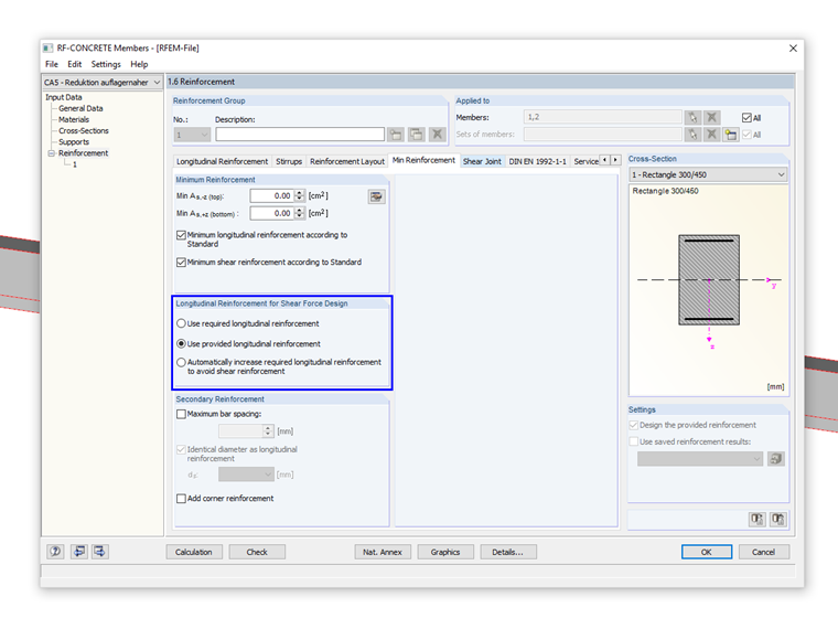
Furthermore, you have the option to increase the required longitudinal reinforcement to avoid a shear reinforcement automatically. Here, the longitudinal reinforcement is increased until the maximum reinforcement ratio of 0.02 is reached. If in this process it is found that VRd,c under the application of the maximum longitudinal reinforcement ratio is still less than the acting shear force VEd, then the increase of the longitudinal reinforcement has no effect on the shear resistance VRd,c and it is not used. In this case, VRd,c is determined with the required longitudinal reinforcement from the bending analysis, and then the required shear reinforcement is calculated.
Links
Write Comment...
Write Comment...
Contact us
Do you have questions or need advice?
Contact our free e-mail, chat, or forum support or find various suggested solutions and useful tips on our FAQ page.
Recommended Events
Videos
Models to Download
Knowledge Base Articles

New
User-Defined Link Spacings
To cover the required transverse reinforcement, RF‑CONCRETE Members and CONCRETE determine the most cost-efficient transverse reinforcement as reinforcement proposal in accordance with the predefined stirrup diameter.
Screenshots
Product Features Articles

Material Model Orthotropic Masonry 2D
The material model Orthotropic Masonry 2D is an elastoplastic model that additionally allows softening of the material, which can be different in the local x- and y-direction of a surface. The material model is suitable for (unreinforced) masonry walls with in-plane loads.
Frequently Asked Questions (FAQ)
- How do you define the descriptions of various reinforcement results,such as the required reinforcement?
- How are the creep and shrinkage for columns considered in RF‑CONCRETE Members?
- How can I display the vertical deformation of a column in state II? I cannot find this setting for the serviceability limit state design.
- Is the preset crack width of, for example, wk = 0.3 mm also designed for primary cracks? According to the manual, the average strain is considered. Does this ensure that the primary crack does not exceed the value wk = 0.3 mm?
- For the design of a ring beam, I usually have Mz moments, which causes the formation of the compression and tension zone on the right and left of the cross-section. However, the reinforcement in CONCRETE is arranged at the top and bottom of the cross-section. How can I set the reinforcement to be arranged on the right and left?
- When calculating deformations in RF‑CONCRETE Members, I get jumps in the deformation diagram. Why?
- Why can I no longer display the intermediate results in RF‑CONCRETE Members?
- Can I use RF‑CONCRETE Surfaces to determine the steel mass for the inserted reinforcement?
- In connection with the analytical SLS calculation, I get implausibly large values for the crack width and deformation in the RF‑CONCRETE add-on modules. What is the cause and how can I fix the problem?
- How do I find the non-designable locations in the work window?