Design Format According to General Method by 6.3.4
The design according to the General Method is performed by reducing the system's load-bearing capacity in its main load-bearing plane by the reduction factor χop, which takes into account the stability failure from the plane.
(χop ⋅ αult,k) / γM1 ≥ 1.0
χop... Reduction factor for buckling and lateral-torsional buckling from the plane
αult,k... The magnification factor for the design values of loading by which the characteristic load-bearing capacity of structural components with deformations in the structural system's plane is achieved
γM1... Partial safety factor for stability designs
Considering stability failure also in the plane of the structural system must, therefore, be done in the calculation of the magnification factor αult,k. If necessary, all imperfections and effects according to second-order analysis occurring in the structural system's plane must be taken into account when determining internal forces and moments.
Calculation of Magnification Factor αult,k
The magnification factor is calculated from the design internal forces and moments, as well as the structural components' characteristic resistances within the structure in its main load-bearing plane.
1 / αult,k = NEd / NRk + My,Ed / My,Rk
αult,k... The magnification factor for design values of loading by which the characteristic load-bearing capacity of structural components with deformations in the structural system's plane is achieved
Ned... Design value of acting normal force
Nrk... Characteristic normal force resistance
My,Ed... Design value of acting bending moment around y-axis
My,Rk... Characteristic moment resistance around y-axis
Checking the Need to Consider Flexural Buckling in the Main Load-Bearing Plane
In order to estimate the influence of the effects according to the second-order analysis on the internal forces and moments in the main supporting plane, the corresponding magnification factor αcr can be calculated as a comparison value. According to the rules in EN 1993-1-1, it is not necessary to consider flexural buckling in the main supporting plane for an elastic determination of internal forces if this factor exceeds the limit value of 10.
αcr,ip ≥ 10
αcr,ip... The magnification factor by which the design values of the loading would have to be increased in order to achieve the elastic critical buckling load for stability failure in the main load-bearing plane
In RFEM and RSTAB, the mode shapes and the corresponding magnification factor can be determined using RF-STABILITY and RSBUCK. If all mode shapes with load factors smaller than 10 are characterized by a deflection perpendicular to the main load-bearing plane, the magnification factors for stability failure in the main load-bearing plane are above this limit value and this case does not have to be considered in the design.
Applying Imperfections in Main Load-Bearing Plane
If stability failure is to be analyzed in the main load-bearing plane, the internal forces and moments must be determined according to the second-order analysis by applying the necessary equivalent imperfections according to Section 5.3.2 of EN 1993-1-1. In the design, they are directly taken into account by the magnification factor αult,k, which is now correspondingly smaller.
In this context, it is important to correctly apply the equivalent imperfections, which have to be applied on the structure in their most unfavorable effect. Where required, several variants have to be considered.
Example of Tapered Frame
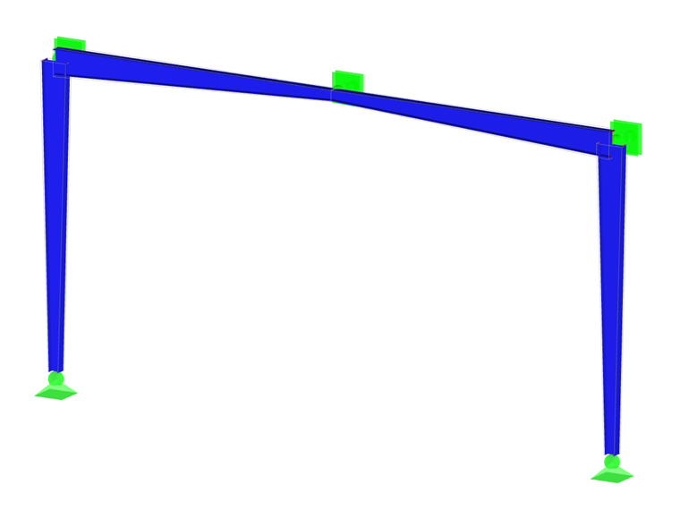
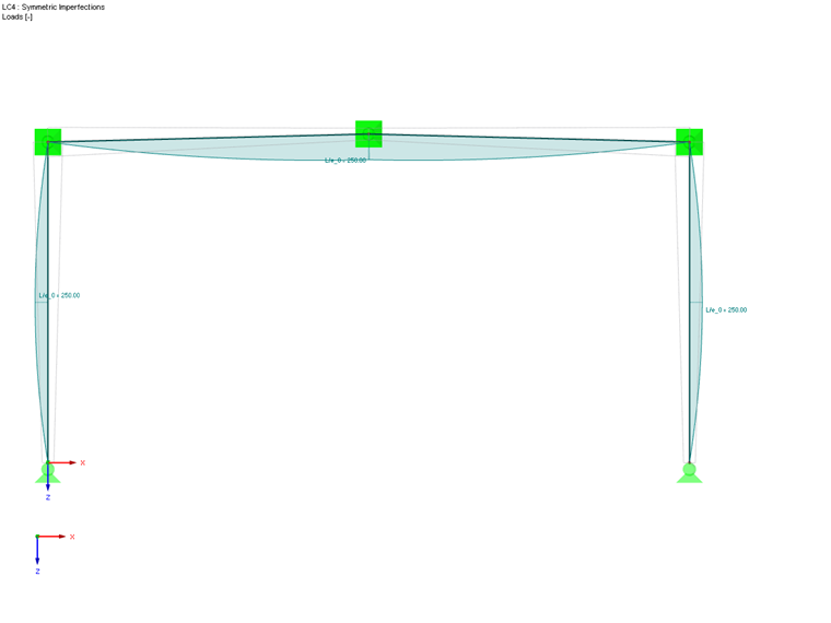
For a hall frame with tapers at the frame joints, the stability analysis should be performed according to the General Method. First, the magnification factor for buckling in the frame plane is determined under the governing loading.
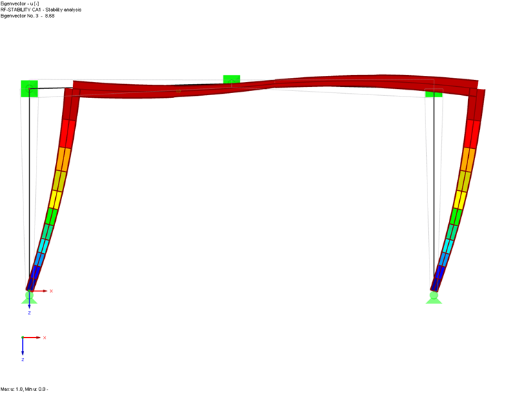
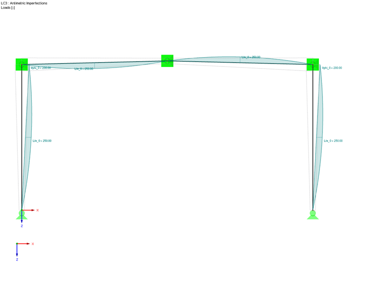
The factor is 8.7 and thus below the limit value of 10. As a result, the internal forces and moments must be determined according to the second-order analysis by applying the imperfections in the frame plane. In order to consider both a symmetric and an antimetric buckling shape of the frame, two different imperfection shapes are applied. These shapes result from the frame columns' inclination and precambers according to the most unfavorable buckling curve of the cross-sections according to Table 5.1.
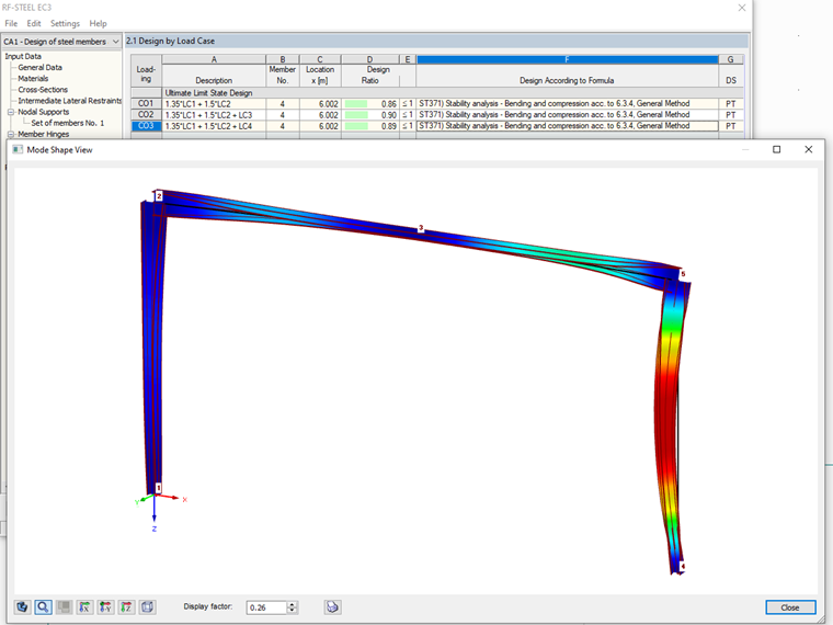
Using these internal forces and moments, you can now perform the stability analysis according to the General Method. To do this, select the entire frame as a set of members for design, and set the nodal supports in accordance with the main model.
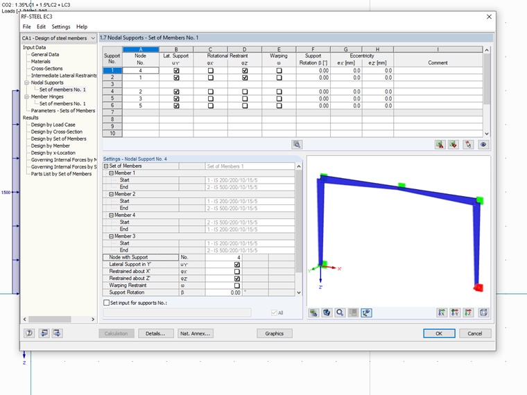
With the help of the eigenvalue resolver, the magnification factor αcr,op is determined and used for the designs at each x-location of the set of members. The corresponding mode shape can be checked in the graphical view.