Consider Rail Section
Technical Article
In CRANEWAY, the action of a rail as "statically effective" or "statically ineffective" is defined under "Rail‑Flange Connection" in the Details dialog box. This setting controls the calculation of the load introduction length according to EN 1993‑6, Tab. 5.1.
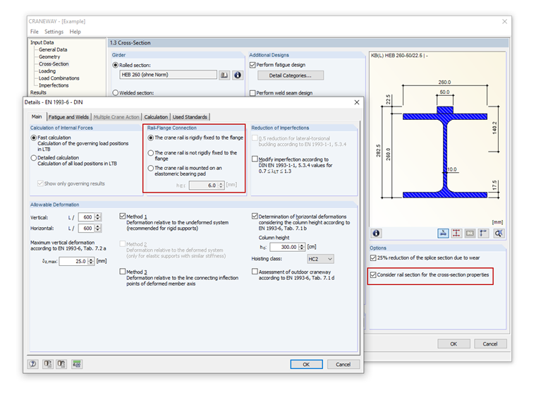
However, the selection is irrespective of the "Consider rail section for the cross‑section properties" option in Window 1.3. If the cross-section values including rails are determined, this has an effect on the internal forces and deformations.
Author

Dipl.-Ing. (FH) René Flori
Head of Customer Support
Mr. Flori is the customer support team leader and also provides technical support for customers of Dlubal Software.
Keywords
Length of wheel load distribution Buckling design for web Crane runway rail Fastening
Downloads
Links
Write Comment...
Write Comment...
Contact Us
Do you have any further questions or need advice? Contact us via phone, email, chat or forum or find suggested solutions and useful tips on our FAQ page, available 24/7.

When using interrupted welds between the rail and flange, make sure that the applied weld length does not exceed the length of the rigid load application of the wheel load according to Equation 6.1 in [1].

- Craneway and weld stress analysis
- Craneways and weld fatigue design
- Deformation analysis
- Plate buckling analysis for wheel load introduction
- Stability analysis for lateral torsional buckling according to the second-order analysis of torsional buckling (1D FEA element)
For the design according to Eurocode 3, the following National Annexes are available:
-
DIN EN 1993-6/NA:2010-12 (Germany)
NBN EN 1993-6/ANB:2011-03 (Belgium)
-
SFS EN 1993-6/NA:2010-03 (Finland)
NF EN 1993-6/NA:2011-12 (France)
UNI EN 1993-6/NA:2011-02 (Italy)
LST EN 1993-6/NA:2010-12 (Lithuania)
NEN EN 1993-6/NB:2012-05 (The Netherlands)
NS EN 1993-6/NA:2010-01 (Norway)
SS EN 1993-6/NA:2011-04 (Sweden)
CSN EN 1993-6/NA:2010-03 (Czech Republic)
BS EN 1993-6/NA:2009-11 (United Kingdom)
CYS EN 1993-6/NA:2009-03 (Cyprus)
In addition to the National Annexes (NA) listed above, you can also define a specific NA, applying user-defined limit values and parameters.
- Where is the fatigue design activated in the CRANEWAY program?
- How can I optimize the calculation time in CRANEWAY?
- Where can I find the determined support forces for the crane runway girder? At the bottom flange of the crane runway girder or in the shear center of the cross-section?
- Is it possible to manually adjust detail categories or a stress cycle of the detail categories?
- How can I obtain internal forces, calculated in CRANEWAY, for a special x-location?
- I am trying to manually check the deformations from the CRANEWAY add-on module. However, I obtain major deviations. How are the differences explained?
- How can I model and design a crane runway girder with Dlubal Software?
- Is it possible to design intermittent welds in the CRANEWAY add-on module?
- Is it necessary to enter the loads of a crane for each axle or wheel in the table of crane loads in Window 1.4?
- Is it possible to design a crane runway girder without stiffeners on supports in CRANEWAY?
Associated Products